3.8
BLADE BRUSH ADJUSTMENT
The blade brush is properly set when the machine leaves the factory, but wears during
operation and needs to be re-adjusted periodically. The plastic wheel that is driven
by the idler wheel face should be held against the idler wheel with the minimum force
that is necessary. As the blade brush wears it is necessary to adjust it closer to the
blade, or further away from the blade if a new brush is installed.
As shown, there are two springs on socket head screws holding the brush against the
blade. There is also an adjusting socket set screw with a hex nut on it. Adjustment is
made from the back side by loosening the hex nut and turning the set screw. Tight-
ening the set screw will move the brush away from the blade, and loosening the set
screw will move the brush closer to the blade. Adjust the set screw so that the brush
cleans to the bottom of the blade gullets and then tighten the hex nut.
BLADE WIPERS
Two blade wiper assemblies are mounted close to the idler wheel to remove coolant from the
blade. As the urethane wipers wear, the angular position of the assemblies may be adjusted
to maintain contact with the blade. The wipers may be flipped over and rotated end for end to
provide four successive wiping edges before they must be replaced. Rubber has a very short life
in this application and it is recommended that genuine urethane wipers be obtained from your
dealer.
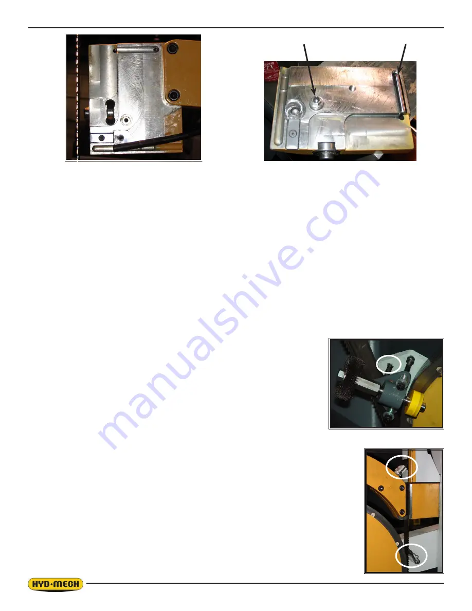
Removal of the front plate completely exposes the internals of the guide block assembly as shown in the photos above.
The side carbides are mounted by #6-32 flat head socket screws which engage lock nuts on the outside of the plates. The
back plate holds the square pivoting carbide insert that correspond to the “top” carbide in horizontal machines. A dowel pin
pressed into the rear plate locates the pivoting carbide. This carbide can be rotated four times to offer four new surfaces
before it is replaced.
The adjusting screw assembly should not normally need to come apart. If dis-assembly is required, be aware that the nut,
and circular nut above it are both locked with red Loctite
271, and similar material must be used at re-assembly.
The hinge between the front and rear plates of the guide assembly is formed by a dowel pin resting in two semi circular
grooves. For convenience during disassembly, the pin is “glued” into the groove of the front plate using Loctite
515 Gas-
ket Eliminator.
When re-installing the front plate, support the plate with one hand while locating the adjusting screw in its tapped hole,
and then turning it in 6 – 7 turns before installing the hinge screws. This avoids the possibility of cross-threading or bend-
ing the adjusting screw.
Dowel Pin - Hinge
Adjusting Screw Assembly
Содержание V-25APC
Страница 2: ......
Страница 13: ...0 9 ...
Страница 16: ...0 12 ...
Страница 59: ...4 1 ELECTRICAL SCHEMATICS SEE PDF ON ATTACHED CD SECTION 4 ELECTRICAL ...
Страница 60: ......
Страница 63: ...6 1 MECHANICAL ASSEMBLY DRAWINGS PARTS LIST SEE PDF ON ATTACHED CD SECTION 6 MECHANICAL ASSEMBLIES ...
Страница 64: ......
Страница 72: ...8 2 V 25APC 5 BARFEED LAYOUT SHEET 1 ...
Страница 73: ...8 3 V 25APC 5 BARFEED LAYOUT SHEET 2 ...
Страница 74: ...8 4 V 25APC 10 BARFEED LAYOUT SHEET 1 ...
Страница 75: ...8 5 V 25APC 10 BARFEED LAYOUT SHEET 2 ...
Страница 76: ...8 6 ...
Страница 78: ......


