2.11
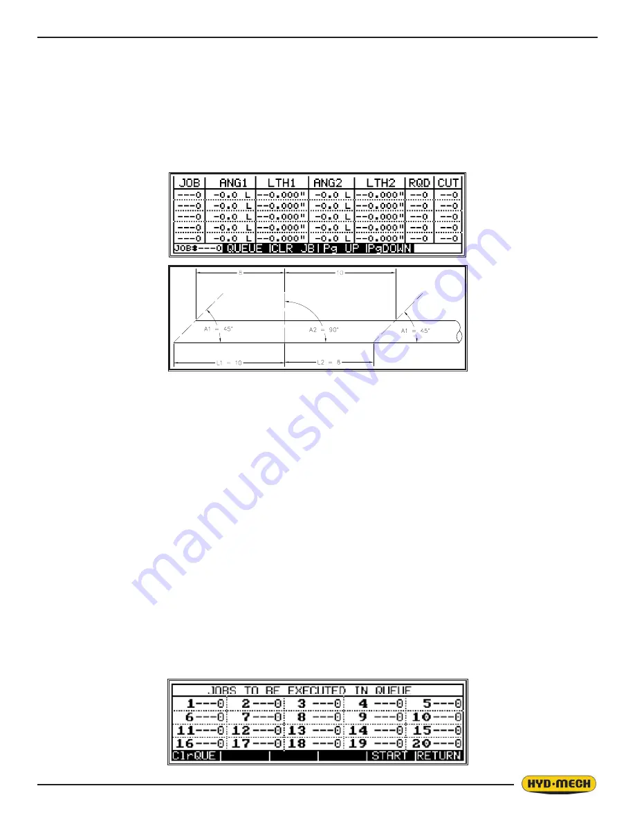
3. Immediately after entering the AUTO mode, the JOB screen will be displayed with the cursor located at “A1 of
JOB #1” (See Below). Both the ENTER button or the cursor key can be used to move through this screen.
There are three ways to navigate between pages:
•
PG UP (Page Up) – Pressing this key will cause the display to scroll up.
•
PG DOWN (Page Down) - Pressing this key will cause the display to scroll down.
•
JOB 0 (JOB search function). Enter the job number that you want to display/edit and then press enter.
The required Job number will be displayed on the screen.
To CLEAR JOB parameters – Move the cursor to the required job number, and then press the CLR JB (Clear Job)
button.
4. Enter proper “A1” value, press ENTER and the cursor will move to angle direction letter.
5. Press ENTER to toggle between R (right) and L (left). To move to “L1”, use the cursor key.
6. Enter proper “L1” value, press ENTER and the cursor will move to “A2”.
7. Enter proper “A2” value, press ENTER and the cursor will move to angle direction letter.
8. Press ENTER to toggle between R (right) and L (left). To move to “L2”, use the cursor key.
9. Enter proper value for “L2”, press ENTER and the cursor will move to “RQD”.
10. Enter required quantity, press ENTER and the cursor will move to “CUT”.
11. When starting a new job, zero out “CUT” quantity by entering “0”.
12. The job is now ready to start to run or other jobs can be programmed at this time. To run a certain job, press the
QUEUE key and then ClrQUE to clear the QUEUE. Move the cursor to the 1
st
job and key in the desired JOB #.
The purpose of a QUEUE is to allow the operator to run several jobs (maximum of 20) in series if they are of the
same material and shape.
To run a QUEUE, it is necessary to program in all job values as is done with programming a single job. After the
jobs are programmed in, press QUEUE, press CLR QUE to clear the previous QUEUE, and enter the desired
JOB #’s in the desired sequence.
JOB LIST
START BLADE FOR TRIM CUT
Содержание V-25APC
Страница 2: ......
Страница 13: ...0 9 ...
Страница 16: ...0 12 ...
Страница 59: ...4 1 ELECTRICAL SCHEMATICS SEE PDF ON ATTACHED CD SECTION 4 ELECTRICAL ...
Страница 60: ......
Страница 63: ...6 1 MECHANICAL ASSEMBLY DRAWINGS PARTS LIST SEE PDF ON ATTACHED CD SECTION 6 MECHANICAL ASSEMBLIES ...
Страница 64: ......
Страница 72: ...8 2 V 25APC 5 BARFEED LAYOUT SHEET 1 ...
Страница 73: ...8 3 V 25APC 5 BARFEED LAYOUT SHEET 2 ...
Страница 74: ...8 4 V 25APC 10 BARFEED LAYOUT SHEET 1 ...
Страница 75: ...8 5 V 25APC 10 BARFEED LAYOUT SHEET 2 ...
Страница 76: ...8 6 ...
Страница 78: ......


