COMANDO GAS
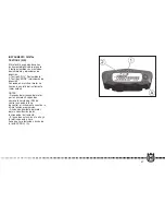
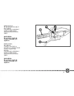
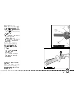
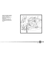
La manopola (1) del gas é situata
sulla parte destra del manubrio.
La posizione del comando sul
manubrio può essere regolata
allentando le due viti di fissaggio.
AVVERTENZA
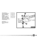
Non dimenticare di stringere le
viti (A) dopo la regolazione.
COMANDO FRENO
ANTERIORE
La leva (2) del freno è situata sul
lato destro del manubrio e
comanda il freno anteriore.
La posizione del comando sul
manubrio può essere regolata
allentando le due viti di fissaggio.
AVVERTENZA
Non dimenticare di stringere le
viti (B) dopo la regolazione.
THROTTLE CONTROL
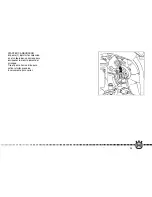
The throttle (1) knob, located on
the right-hand side of the
handlebar.
The position on the
handlebar can be adjusted by
loosening the two fixing screws.
CAUTION
Do not forget to tighten the
screws (A) after the adjustment.
FRONT BRAKE
CONTROL
The brake control lever (2) is
situated on the right-hand side of
the handlebar and controls the
front wheel brake.
The position on the handlebar
can be adjusted by loosening
the two fixing screws.
CAUTION
Do not forget to tighten the
screws (B) after the adjustment.
POIGNEE DES GAZ
La poignée (1) des gaz est
placée à droite du guidon.
La position de la commande sur
le guidon peut être réglée en
desserrant les deux vis de
fixation.
ATTENTION
N’oubliez pas de serrer les vis
(A) après le réglage.
COMMANDE
FREIN AVANT
La manette (2) de commande du
frein avant est placée du côté
droit du guidon.
La position de la commande sur
le guidon peut être réglée en
desserrant les deux vis de
fixation.
ATTENTION
N’oubliez pas de serrer les vis
(B) après le réglage.
GASANLASSER
Der Griff (1) für das Gas, der sich
auf der rechten Seite des Lenkers
befindet.
Die Schaltungs-Position
auf dem Lenker kann durch
Lockern der beiden
Befestigungsschrauben
eingestellt werden.
MAN BEACHTE
Nach der Einstellung nicht
vergessen, die Schrauben (A)
anzuziehen.
STEUERUNG
VORDERBREMSE
Der Bremshebel (2) befindet sich
auf der rechten Seite des Lenkers
und steuert die Vorderbremse.
Die Schaltungs-Position auf dem
Lenker kann durch Lockern der
beiden Befestigungsschrauben
eingestellt werden.
MAN BEACHTE
Nach der Einstellung nicht ver-
gessen, die Schrauben (B)
anzuziehen.
56
IMP. 4-250-300-2009 12-06-2008 14:07 Pagina 56
Содержание 2009 WR 250
Страница 181: ...181 USA CDN B 3 4 5 1 C F D E 2 6 A G IMP 10 250 300 2009 16 06 2008 11 47 Pagina 181 ...
Страница 198: ...198 NOTES FOR USA CDN MODEL IMP 11 250 300 2009 16 06 2008 12 00 Pagina 198 ...
Страница 236: ...MEMORANDUM 236 IMP 13 250 300 2009 13 06 2008 11 26 Pagina 236 ...
Страница 237: ...237 MEMORANDUM IMP 13 250 300 2009 13 06 2008 11 26 Pagina 237 ...
Страница 238: ...MEMORANDUM 238 IMP 13 250 300 2009 13 06 2008 11 26 Pagina 238 ...
Страница 239: ...239 MEMORANDUM IMP 13 250 300 2009 13 06 2008 11 26 Pagina 239 ...
Страница 240: ...240 MEMORANDUM IMP 13 250 300 2009 13 06 2008 11 26 Pagina 240 ...
Страница 241: ...241 MEMORANDUM IMP 13 250 300 2009 13 06 2008 11 26 Pagina 241 ...
Страница 242: ...242 MEMORANDUM IMP 13 250 300 2009 13 06 2008 11 26 Pagina 242 ...

