


AMP(H)41_MANUAL-en_R11
ID 75056
Release date: 2019-03-28
English
Operating and assembly instructions
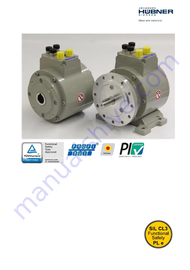
Absolute encoder with
PROFIBUS-DP interface and PROFIsafe protocol
AMP 41
in construction types B5 (flange) and B35 (flange and foot)
AMPH 41 (
hollow shaft design)
Functional safety according to EN 61508: SIL CL3 and EN ISO 13849: PL e
Read the operating and assembly instructions prior to
assembly, starting installation and handling!
Keep for future reference!
Translation of the original operating and assembly instructions
Содержание AMP 41
Страница 96: ...96 AMP H 41_MANUAL en_R11 2019 03 28 Absolute Encoder AMP H 41 16 3 T V certificate...
Страница 97: ...Absolute Encoder AMP H 41 AMP H 41_MANUAL en_R11 2019 03 28 97 16 4 PROFIBUS DP certificate...
Страница 98: ...98 AMP H 41_MANUAL en_R11 2019 03 28 Absolute Encoder AMP H 41 16 5 PROFIsafe certificate...