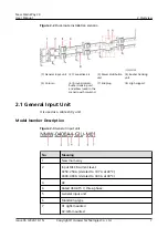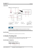
Appearance
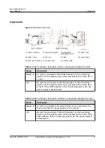
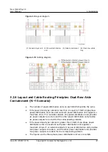
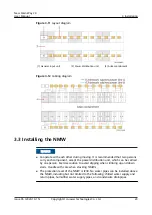
Figure 2-4 General input unit
(1) Alarm indicator
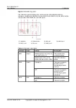
(2) Monitoring panel
(3) Integrated
management card
(4) PWR_2 port
(5) PWR_1 port
(6) FE port
(7) SPD
(8) Input switch
(9) SPD circuit breaker (10) Cable inlet
(11) Cable outlet
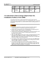
Table 2-1 Alarm indicator description (with an integrated management card)
Status
Description
Steady on
An alarm is generated. If the PWR indicator on the monitoring
panel is on, the general input unit is powered by the mains, 48 V,
or both.
Off
No alarm is generated. If the PWR indicator on the monitoring
panel is on, the general input unit is powered by the mains, 48 V,
or both. If the PWR indicator on the monitoring panel is off, the
power supply is disconnected.
Table 2-2 Alarm indicator description (without an integrated management card)
Status
Description
Steady on
An alarm is generated, the general input unit is powered by the
mains, and the 48 V power supply is not involved.
Off
No alarm is generated. If the PWR indicator on the monitoring
panel is on, the general input unit is powered by the mains. If the
PWR indicator on the monitoring panel is off, the power supply is
disconnected.
New Main Way 2.0
User Manual
2 Overview
Issue 05 (2020-10-15)
Copyright © Huawei Technologies Co., Ltd.
8


