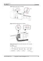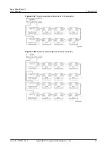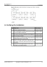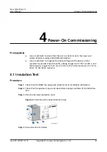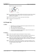
Figure 4-2 Disconnecting the terminals
Step 5 Use a megohmmeter or a device with the same function to measure the insulation
between L and L, L and N, and N and PE. The insulation resistance must be
greater than 500 megohms.
Step 6 After the measurement is complete, interconnect the terminals.
Step 7 Reinstall the input protective cover.
----End
4.2 Power-On
Context
●
Before power-on, ensure that the devices have passed all check items in the
section "Verifying the Installation."
●
Check that all circuit breakers are OFF.
●
Do not switch on the reserved circuit breakers.
●
The Branch Disconnected alarm generated for a reserved circuit breaker can
be masked on the ECC800-Pro WebUI.
Procedure
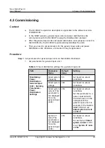
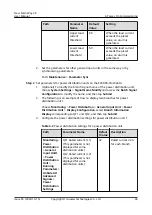
Step 1 Switch on the upstream input circuit breaker for the new main way.
Step 2 Switch on the SPD circuit breaker and input circuit breaker of the new main way
and check that the PWR indicator on the monitoring panel is steady on.
Step 3 Switch on the network cabinet output circuit breaker in the power distribution unit
of the new main way and switch on the rPDU input circuit breaker in the network
cabinet to power on the network cabinet.
Step 4 Switch on the IT cabinet output circuit breakers in the power distribution unit of
the new main way one by one and switch on the rPDU input circuit breaker in the
IT cabinet to power on the IT cabinet.
----End
New Main Way 2.0
User Manual
4 Power-On Commissioning
Issue 05 (2020-10-15)
Copyright © Huawei Technologies Co., Ltd.
44

