Installation Manual
iSiteC BTS3601C CDMA Base Station
Hardware Installation
2
Installing Cabinet Hardware
2-54
II. Plan with the IABB
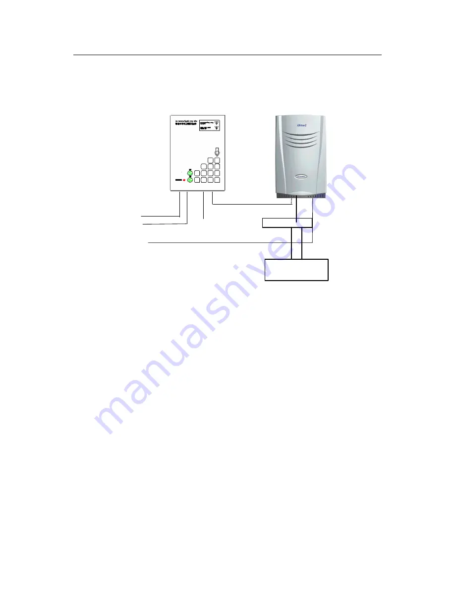
Figure 2-52 shows the connection in this networking mode.
220VAC
BTS3601C 220VAC Input cable
BTS3601C
AC lightning protection box
A pair of fiber cables or E1 cable
Commutator
+24V
GND
Grounding cable
IABB
Figure 2-52
Networking of AC lightning protection box (20kA, with the IABB)
In this plan, the cable connection of AC lightning protection box is completely the same
as that of the IABB. Following is to describe the cable connection between the IABB
and the BTS3601C.
1)
Cable connection between IABB and BTS3601C
Two cables are led out from the IABB. One is of +24V and red, and the other is of GND
and black. Two cables are connected to the DC power cable of the BTS3601C through
a commutator. The +24V cable is interconnected to the red one of the BTS3601C DC
power cable through the red plug of the commutator; and the blcak GND cable is
interconnected to the black one of the BTS3601C power cable through the black pulg of
the commutator. After their interconnections, three types of tapes should be used for
the waterproof of the connections. The detailed processing is available in Section 2.3.6.
2)
Grounding of the IABB
The battery box is generally installed on the platform. In this case, the metal shell of the
box should be grounded, and the PGND wire should be connected to the BTS3601C
grounding busbar from the PGND terminal. The wire should be made of yellow-green
plastic insulation copper wire with the core diameter not less than 16mm
2
. The batteries
inside the box should not be grounded.


