Hardware options installation 39
Hardware options installation
Introduction
If more than one option is being installed, read the installation instructions for all the hardware options
and identify similar steps to streamline the installation process.
WARNING:
To reduce the risk of personal injury from hot surfaces, allow the drives and the
internal system components to cool before touching them.
CAUTION:
To prevent damage to electrical components, properly ground the server before
beginning any installation procedure. Improper grounding can cause electrostatic discharge.
Processor option
The server supports single- and dual-processor operation. With two processors installed, the server
supports boot functions through the processor installed in processor socket 1. However, if processor 1
fails, the system attempts to boot from processor 2 and provides a processor failure message.
The server uses embedded PPMs to provide power to each processor.
CAUTION:
To avoid damage to the processor and system board, only authorized personnel
should attempt to replace or install the processor in this server.
CAUTION:
To avoid damage to the processor:
•
Handle the processor only by the edges.
•
Do not touch the bottom of the processor, especially the contact area.
IMPORTANT:
Processor socket 1 must always be populated. If processor socket 1 is empty, the
server halts during POST.
To install the component:
1.
Power down the server (on page
22
).
2.
Do one of the following:
o
Open or remove the tower bezel, as needed ("
Open or remove the tower bezel
" on page
22
).
o
Extend the server from the rack (on page
24
).
3.
Remove the access panel (on page
25
).
4.
Remove the air baffle (on page
26
).
5.
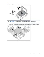
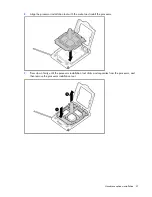
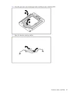
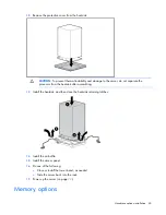
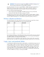
Open the processor retaining latch and the processor socket retaining bracket.
Содержание ProLiant DL370
Страница 1: ...HP ProLiant DL ML370 G6 Server User Guide Part Number 513482 001 March 2009 First Edition ...
Страница 16: ...Component identification 16 SFF hard drives LFF hard drives ...
Страница 29: ...Operations 29 6 Remove the hard drive cage blank ...
Страница 83: ...Hardware options installation 83 o Rear 1 o Front 2 17 Remove the chassis from the tower side panels ...
Страница 94: ...Cabling 94 Drive cage bay 2 Drive cage bay 3 ...
Страница 95: ...Cabling 95 Six bay LFF backplane cabling Drive cage bay 1 Drive cage bay 2 ...
Страница 97: ...Cabling 97 Battery cabling for BBWC DVD ROM drive cabling ...
Страница 98: ...Cabling 98 Slimline optical drive cabling ...
Страница 123: ...Troubleshooting 123 ...
Страница 146: ...Technical support 146 ...
Страница 147: ...Technical support 147 ...

