background image


Troubleshooting 120 

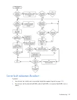
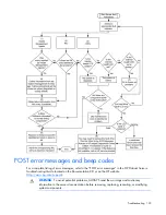
Item Refer 

to 

"General memory problems are occurring" in the 

HP ProLiant Servers 

Troubleshooting Guide

 located on the Documentation CD or on the HP 

website (

http://www.hp.com/support

Server maintenance and service guide, located on the Documentation 

CD or the HP website (

http://www.hp.com/products/servers/platforms


Server maintenance and service guide, located on the Documentation 
CD or the HP website 

(

http://www.hp.com/products/servers/platforms


"Hardware problems" in the 

HP ProLiant Servers Troubleshooting 

Guide

 located on the Documentation CD or on the HP website 

(

http://www.hp.com/support


"Server information you need" in the 

HP ProLiant Servers 

Troubleshooting Guide

 located on the Documentation CD or on the 

HP website (

http://www.hp.com/support


"Operating system information you need" in the 

HP ProLiant Servers 

Troubleshooting Guide

 located on the Documentation CD or on the 

HP website (

http://www.hp.com/support

"HP contact information (on page 

140

)"  


Содержание ProLiant DL370

Страница 1: ...HP ProLiant DL ML370 G6 Server User Guide Part Number 513482 001 March 2009 First Edition ...

Страница 2: ...onstrued as constituting an additional warranty HP shall not be liable for technical or editorial errors or omissions contained herein Microsoft Windows and Windows Server are U S registered trademarks of Microsoft Corporation Intended audience This document is for the person who installs administers and troubleshoots servers and storage systems HP assumes you are qualified in the servicing of com...

Страница 3: ...wer down the server 22 Open or remove the tower bezel 22 Extend the server from the rack 24 Remove the access panel 25 Remove the air baffle 26 Remove the fan cage 26 Remove the media bay blank 27 Remove the DVD ROM drive 28 Remove the hard drive cage blank 28 Setup 30 Optional installation services 30 Rack planning resources 30 Optimum environment 31 Space and airflow requirements 31 Temperature ...

Страница 4: ... bay 3 57 Six bay LFF backplane option 60 Installing the six bay LFF backplane bay 1 60 Installing the six bay LFF backplane bay 2 63 Two bay LFF drive cage option 65 Removable media device options 68 Installing a half height media device 68 Installing a full height media device 70 Slimline optical drive option 71 Expansion board options 73 HP NC524SFP Dual Port 10GbE Module option 75 Storage cont...

Страница 5: ...07 Diagnostic tools 108 HP Insight Diagnostics 108 HP Insight Diagnostics survey functionality 108 Integrated Management Log 108 Array Diagnostic Utility 109 Remote support and analysis tools 109 HP Insight Remote Support software 109 Keeping the system current 109 Drivers 109 ProLiant Support Packs 110 Operating system version support 110 HP Smart Update Manager 110 System Online ROM flash compon...

Страница 6: ...waste equipment by users in private households in the European Union 132 Japanese notice 133 BSMI notice 133 Korean notice 133 Chinese notice 134 Laser compliance 134 Battery replacement notice 134 Taiwan battery recycling notice 135 Power cord statement for Japan 135 Electrostatic discharge 136 Preventing electrostatic discharge 136 Grounding methods to prevent electrostatic discharge 136 Specifi...

Страница 7: ...identification Front panel components Item Description 1 USB connectors 2 2 Drive cage blank 3 SAS SATA drives 8 4 Front video connector rack model only 5 Systems Insight Display 6 Removable media bay 7 DVD ROM drive 8 Optical drive blank ...

Страница 8: ...reen Normal system on Amber System in standby but power still applied Off Power cord not attached or power supply failure 2 Health LED Green Normal system on Amber System health is degraded Red System health is critical Off Normal system off 3 UID LED Blue Activated Flashing blue System is being managed remotely Off Deactivated ...

Страница 9: ...ll LEDs flashing DIMM unseated All other LEDs Amber Failure Off Normal IMPORTANT If more than one DIMM slot LED is illuminated further troubleshooting is required Test each bank of DIMMs by removing all other DIMMs Isolate the failed DIMM by replacing each DIMM in a bank with a known working DIMM Systems Insight Display LED combinations When the health LED on the front panel illuminates either amb...

Страница 10: ...r Green One fan has failed or has been removed Fan amber Red Green Two or more fans have failed or been removed Power supply amber Red Amber Only one power supply is installed and that power supply is in standby Power supply fault System board fault Power supply amber Amber Green Redundant power supply is installed and only one power supply is functional AC power cord is not plugged into redundant...

Страница 11: ...ponents Item Description 1 Mouse connector 2 Keyboard connector 3 Serial connector 4 iLO 2 connector 5 USB connectors 2 6 NIC connectors 4 7 PCI expansion slots 8 Reserved 9 Video connector 10 Power supply bay 2 11 Power supply bay 1 populated ...

Страница 12: ...een Network activity Off No network activity 3 iLO 2 link LED Green Linked to network Off No network connection 4 NIC link LED Green Linked to network Off No network connection 5 NIC activity LED Green or flashing green Network activity Off No network activity 6 Power supply LED Green System has AC power and is powered up Off System has no AC power the system is off or the power supply has failed ...

Страница 13: ...el connector 8 Systems Insight Display connector 9 Front video connector 10 Front USB connector 11 Smart Array P410i memory module 12 Reserved 13 System battery 14 TPM connector 15 SATA connectors 6 16 Slot 1 PCIe x8 4 2 1 17 Slot 2 PCIe2 x8 4 2 1 18 Slot 3 PCIe2 x16 16 8 4 2 1 19 System maintenance switch 20 Slot 4 PCIe2 x8 4 2 1 21 Slot 5 PCIe2 x8 4 2 1 22 Slot 6 PCIe2 x16 8 4 2 1 23 Slot 7 PCIe...

Страница 14: ...a ten position switch that is used for system configuration Position Description Function S1 iLO security Off iLO security is enabled On iLO security is disabled S2 Configuration lock Off System configuration can be changed On System configuration is locked S3 Rack Tower ID Off Tower On Rack S4 Reserved Reserved S5 Password protection override Off No function On Clears power on password and admini...

Страница 15: ...ations Many crashes freeze a system and the only available action for administrators is to cycle the system power Resetting the system erases any information that could support problem analysis but the NMI feature preserves that information by performing a memory dump before a hard reset To force the OS to invoke the NMI handler and generate a crash dump log the administrator can do any of the fol...

Страница 16: ...Component identification 16 SFF hard drives LFF hard drives ...

Страница 17: ...TA hard drive LED combinations Online activity LED green Fault UID LED amber blue Interpretation On off or flashing Alternating amber and blue The drive has failed or a predictive failure alert has been received for this drive it also has been selected by a management application On off or flashing Steadily blue The drive is operating normally and it has been selected by a management application O...

Страница 18: ...r it is part of an array that is undergoing capacity expansion or stripe migration Flashing irregularly Amber flashing regularly 1 Hz The drive is active but a predictive failure alert has been received for this drive Replace the drive as soon as possible Flashing irregularly Off The drive is active and it is operating normally Off Steadily amber A critical fault condition has been identified for ...

Страница 19: ...Component identification 19 Fans Item Description Configuration 1 Fan 1 Redundant 2 Fan 2 Primary 3 Fan 3 Redundant 4 Fan 4 Primary 5 Fan 5 Primary Battery pack LEDs ...

Страница 20: ...ache module size For further information refer to the controller QuickSpecs on the HP website http www hp com Double blink then pause The cache microcontroller is waiting for the host controller to communicate One blink per second The battery pack is below the minimum charge level and is being charged Features that require a battery such as write cache capacity expansion stripe size migration and ...

Страница 21: ...wer supply 1 cable P2 Power supply 2 cable P6 SATA power cable P7 SATA power cable P8 SATA power cable P9 Video adapter power cable P10 Data cable P12 Video adapter power cable Drive cage jumper configuration settings Drive cage Installation Pin setting 1 Standard No jumper 2 Optional 1 2 3 Optional 2 3 Optional drive cages ship with the jumper set across pins 1 and 2 ...

Страница 22: ...s directed by the operating system documentation NOTE If the operating system automatically places the server in Standby mode omit the next step 3 Press the Power On Standby button to place the server in Standby mode When the server activates Standby power mode the system power LED changes to amber IMPORTANT Pressing the UID button illuminates the blue UID LEDs on the front and rear panels In a ra...

Страница 23: ...Operations 23 Use the key provided with the server to unlock the bezel with a counterclockwise turn If necessary remove the tower bezel ...

Страница 24: ... from the rack to access internal components 1 Extend the server on the rack rails until the server rail release latches engage WARNING To reduce the risk of personal injury or equipment damage be sure that the rack is adequately stabilized before extending a component from the rack WARNING To reduce the risk of personal injury be careful when pressing the server rail release latches and sliding t...

Страница 25: ...surfaces allow the drives and the internal system components to cool before touching them CAUTION Do not operate the server for long periods with the access panel open or removed Operating the server in this manner results in improper airflow and improper cooling that can lead to thermal damage To remove the component 1 Do one of the following o Open or remove the tower bezel as needed Open or rem...

Страница 26: ...2 Do one of the following o Open or remove the tower bezel as needed Open or remove the tower bezel on page 22 o Extend the server from the rack on page 24 3 Remove the access panel on page 25 4 Remove the air baffle Remove the fan cage 1 Power down the server on page 22 2 Do one of the following o Open or remove the tower bezel as needed Open or remove the tower bezel on page 22 o Extend the serv...

Страница 27: ...n the server on page 22 2 Do one of the following o Open or remove the tower bezel as needed Open or remove the tower bezel on page 22 o Extend the server from the rack on page 24 3 Remove the access panel on page 25 4 Remove the media bay blank Save the blank for future use ...

Страница 28: ...e the air baffle on page 26 5 Remove the fan cage on page 26 6 Disconnect and remove the DVD ROM drive data power cable 7 Remove the DVD ROM drive Remove the hard drive cage blank 1 Power down the server on page 22 2 Do one of the following o Open or remove the tower bezel as needed Open or remove the tower bezel on page 22 o Extend the server from the rack on page 24 3 Remove the access panel on ...

Страница 29: ...Operations 29 6 Remove the hard drive cage blank ...

Страница 30: ...l to Repair o 4 Hour 24x7 Same Day o 4 Hour Same Business Day Software support o Microsoft o Linux o HP ProLiant Essentials HP SIM and RDP o VMWare Integrated hardware and software support o Critical Service o Proactive 24 o Support Plus o Support Plus 24 Startup and implementation services for both hardware and software For more information on Care Packs refer to the HP website http www hp com hp...

Страница 31: ...ce in the rack is not filled by a server or rack component the gaps between the components cause changes in airflow through the rack and across the servers Cover all gaps with blanking panels to maintain proper airflow CAUTION Always use blanking panels to fill empty vertical spaces in the rack This arrangement ensures proper airflow Using a rack without blanking panels results in improper cooling...

Страница 32: ...vides power to the rack Consult the electrical authority having jurisdiction over wiring and installation requirements of your facility CAUTION Protect the server from power fluctuations and temporary interruptions with a regulating uninterruptible power supply UPS This device protects the hardware from damage caused by power surges and voltage spikes and keeps the system in operation during a pow...

Страница 33: ...damage when unloading a rack At least two people are needed to safely unload the rack from the pallet An empty 42U rack can weigh as much as 115 kg 253 lb can stand more than 2 1 m 7 ft tall and may become unstable when being moved on its casters Never stand in front of the rack when it is rolling down the ramp from the pallet Always handle the rack from both sides WARNING When installing a server...

Страница 34: ... improper cooling that can lead to thermal damage Identifying tower server shipping carton contents Unpack the server shipping carton and locate the materials and documentation necessary for installing the server The contents of the server shipping carton include Server Power cord Keyboard Mouse Tower feet Hardware documentation Documentation CD and software products In addition to the supplied it...

Страница 35: ...odel server If you are going to install the server into a rack refer to the rack installation section Installing the server into the rack on page 36 1 Place the server on a flat stable surface 2 Install the the tower feet 3 Connect peripheral devices to the server Rear panel components on page 11 WARNING To reduce the risk of electric shock fire or damage to the equipment do not plug telephone or ...

Страница 36: ...by items placed against it Pay particular attention to the plug electrical outlet and the point where the cord extends from the server Installing the server into the rack To install the server into a rack with square round or threaded holes refer to the instructions that ship with the rack hardware kit If you are installing the server into a telco rack order the appropriate option kit at the RackS...

Страница 37: ...gured to prepare the server for operating system installation To configure these utilities manually Press the F8 key when prompted during the array controller initialization to configure the array controller using ORCA Press the F9 key when prompted during the boot process to change the server settings using RBSU The system is set up by default for the English language For more information on the ...

Страница 38: ...Setup 38 Registering the server To register the server refer to the HP Registration website http register hp com ...

Страница 39: ... However if processor 1 fails the system attempts to boot from processor 2 and provides a processor failure message The server uses embedded PPMs to provide power to each processor CAUTION To avoid damage to the processor and system board only authorized personnel should attempt to replace or install the processor in this server CAUTION To avoid damage to the processor Handle the processor only by...

Страница 40: ...0 6 Remove the processor socket protective cover IMPORTANT Be sure the processor remains inside the processor installation tool 7 If the processor has separated from the installation tool carefully re insert the processor in the tool ...

Страница 41: ... 41 8 Align the processor installation tool with the socket and install the processor 9 Press down firmly until the processor installation tool clicks and separates from the processor and then remove the processor installation tool ...

Страница 42: ...Hardware options installation 42 10 Close the processor socket retaining bracket and the processor retaining latch 11 Open the heatsink retaining latches ...

Страница 43: ...do not separate the processor from the heatsink after assembling 13 Install the heatsink and then close the heatsink retaining latches 14 Install the air baffle 15 Install the access panel 16 Do one of the following o Close or install the tower bezel as needed o Slide the server back into the rack 17 Power up the server on page 22 Memory options ...

Страница 44: ...annel supports three DIMM slots as shown in the following table Channel Slot Slot number 1 G D A 1 2 3 2 H E B 4 5 6 3 I F C 7 8 9 This multi channel architecture provides enhanced performance in Advanced ECC mode This architecture also enables the Mirrored Memory and Lockstep memory modes This server supports both Registered PC3 DIMMSs RDIMMs and Unbuffered DIMMs UDIMMs DIMM slots in this server ...

Страница 45: ...n The memory subsystem may be populated with either RDIMMs or UDIMMs but mixing the two types is not supported To determine DIMM characteristics use the label attached to the DIMM and the following illustration and table Item Description Definition 1 Size 2 Rank 1R Single rank 2R Dual rank 4R Quad rank 3 Data width x4 4 bit x8 8 bit 4 Memory speed 10600 1333 MHz 8500 1067 MHz 5 DIMM type R RDIMM r...

Страница 46: ... GB 144 GB Dual rank 72 GB 144 GB Quad rank 48 GB 96 GB UDIMM maximum memory configurations The server supports a maximum of 12 GB with one processor and 24 GB with two processors using 2 GB single or dual rank UDIMMs Advanced ECC memory configuration Advanced ECC memory is the default memory protection mode for this server Standard ECC can correct single bit memory errors and detect multi bit mem...

Страница 47: ...e installed first on that channel DIMM speeds are supported as indicated in the following table Populated slots per channel Rank Speeds supported MHz 1 Single or dual rank 1333 1066 1 Quad rank 1066 2 Single or dual rank 1066 3 Single or dual rank 800 Advanced ECC population guidelines For Advanced ECC mode configurations observe the following guidelines Observe the general DIMM slot population gu...

Страница 48: ...or Lockstep memory mode configurations with a single processor populate the DIMM slots in the following order RDIMM o First A and B o Next D and E o Last G and H o Do not populate slots C F or I UDIMM o First A and B o Last D and E o Do not populate slots C F G H or I After installing the DIMMs use RBSU to configure the system for Lockstep memory support Configuring lockstep memory on page 101 Mul...

Страница 49: ...u are installing DIMMs in lock step configuration configure this mode in RBSU HP ROM Based Setup Utility on page 100 For more information about LEDs and troubleshooting failed DIMMs see Systems Insight Display LEDs and internal health LED combinations Systems Insight Display LED combinations on page 9 Redundant hot plug fans option The server supports redundant hot plug fans to provide proper airf...

Страница 50: ...s with insulated handles Do not place tools or metal parts on top of batteries To install the component 1 Power down the server on page 22 2 Do one of the following o Open or remove the tower bezel as needed Open or remove the tower bezel on page 22 o Extend the server from the rack on page 24 3 Remove the access panel on page 25 4 Remove the air baffle on page 26 5 Remove the fan cage on page 26 ...

Страница 51: ...ord grounding plug The grounding plug is an important safety feature Plug the power cord into a grounded earthed electrical outlet that is easily accessible at all times Unplug the power cord from the power supply to disconnect power to the equipment Do not route the power cord where it can be walked on or pinched by items placed against it Pay particular attention to the plug electrical outlet an...

Страница 52: ... power supplies have the same part number and label color The system becomes unstable and may shut down when it detects mismatched power supplies Label color Output Blue 460W Orange 750W Green 1 200W Hot plug power supply calculations For more information on the hot plug power supply and calculators to determine server power consumption in various system configurations refer to the HP Enterprise C...

Страница 53: ...Ds on page 12 IMPORTANT For maximum server availability be sure that the two power supplies are powered by separate AC power sources Hot plug SAS hard drive options When adding hard drives to the server observe the following general guidelines The system automatically sets all device numbers If only one hard drive is used install it in the bay with the lowest device number Drives should be the sam...

Страница 54: ...of the hard drive from the hot plug SAS hard drive LED combinations SAS and SATA hard drive LED combinations on page 17 Removing a hot plug SAS hard drive CAUTION For proper cooling do not operate the server without the access panel baffles expansion slot covers or blanks installed If the server supports hot plug components minimize the amount of time the access panel is open ...

Страница 55: ...d reseller To configure this option for drive cage bay 3 locate the three jumper pins on the backplane Move the jumper from pins 1 and 2 to pins 2 and 3 For more information see Drive cage jumper configuration settings on page 21 Installing the eight bay SFF drive cage bay 2 1 Power down the server on page 22 2 Do one of the following o Open or remove the tower bezel as needed Open or remove the t...

Страница 56: ...Hardware options installation 56 Save the screws 8 Using the screws install the eight bay SFF drive cage 9 Connect the SAS cables to an optional SAS controller Storage controller option on page 78 ...

Страница 57: ...stall the hard drives and hard drive blanks 16 Power up the server on page 22 Installing the eight bay SFF drive cage bay 3 To configure this option for drive cage bay 3 locate the three jumper pins on the backplane Move the jumper from pins 1 and 2 to pins 2 and 3 For more information see Drive cage jumper configuration settings on page 21 1 Power down the server on page 22 2 Do one of the follow...

Страница 58: ...options installation 58 7 Remove the DVD ROM drive on page 28 8 Using a T 10 Torx screwdriver remove the two screws on top of the drive cage 9 Using a T 15 Torx screwdriver remove the sleeve from the drive cage ...

Страница 59: ...re options installation 59 10 Install the drive cage 11 Using a T 15 Torx screwdriver install the locking brackets 12 Connect the SAS cables to an optional SAS controller Storage controller option on page 78 ...

Страница 60: ...ss all bays are populated with either a component or a blank 18 Install the hard drives and hard drive blanks 19 Power up the server on page 22 Six bay LFF backplane option When installing a single six bay LFF backplane HP recommends installing it in drive cage bay 1 When installing a second six bay LFF backplane one of the following options is required An optional SAS controller An optional 24 po...

Страница 61: ...cess panel on page 25 4 Remove the air baffle on page 26 5 Remove the fan cage on page 26 6 Remove any SFF hard drives if installed 7 Disconnect the power and data cables from the eight bay SFF drive cage in drive cage bay 1 8 Using a T 10 Torx screwdriver remove the eight bay SFF drive cage from drive cage bay 1 9 Using a T 15 Torx screwdriver install the six bay LFF backplane ...

Страница 62: ...l the access panel 15 Do one of the following o Close or install the tower bezel as needed o Slide the server back into the rack CAUTION To prevent improper cooling and thermal damage do not operate the server unless all bays are populated with either a component or a blank 16 Install the hard drives and hard drive blanks 17 Power up the server on page 22 ...

Страница 63: ...en or remove the tower bezel as needed Open or remove the tower bezel on page 22 o Extend the server from the rack on page 24 3 Remove the access panel on page 25 4 Remove the air baffle on page 26 5 Remove the fan cage on page 26 6 Remove the hard drive cage blank on page 28 7 Using a T 15 Torx screwdriver install the six bay LFF backplane 8 Connect the power cable ...

Страница 64: ...0 Route and connect the SAS cables 11 Install the fan cage 12 Install the air baffle 13 Install the access panel 14 Do one of the following o Close or install the tower bezel as needed o Slide the server back into the rack CAUTION To prevent improper cooling and thermal damage do not operate the server unless all bays are populated with either a component or a blank 15 Install the hard drives and ...

Страница 65: ...ponent 1 Power down the server on page 22 2 Do one of the following o Open or remove the tower bezel as needed Open or remove the tower bezel on page 22 o Extend the server from the rack on page 24 3 Remove the access panel on page 25 4 Remove the air baffle on page 26 5 Remove the fan cage on page 26 6 Remove all SFF drives and drive cages if installed For more information see the server maintena...

Страница 66: ...rive cage backplane 12 Connect the two bay LFF drive cage to one of the following o A six bay LFF backplane See step 13 o An optional SAS controller See step 14 13 Connect the SAS SATA controller cable a Connect the 6LFF labeled connector to SAS connector 5 6 on the six bay LFF backplane b Connect the 2LFF labeled connector to the two bay LFF drive cage backplane ...

Страница 67: ...the two bay LFF drive cage backplane and to the six bay LFF backplane e Proceed to step 15 14 Connect the SAS SATA controller cable a Connect the main branch of the SAS SATA controller cable to an optional SAS controller Storage controller option on page 78 b Connect the 6LFF labeled connector to the two bay LFF drive cage backplane ...

Страница 68: ...s all bays are populated with either a component or a blank 19 Install the hard drives and hard drive blanks 20 Power up the server on page 22 Removable media device options The server supports the installation of up to two half height devices or one full height device in the removable media bays Installing a half height media device 1 Power down the server on page 22 2 Do one of the following o O...

Страница 69: ...e part of the way into the bay 9 Connect the server data and power cables to the rear of the device 10 Slide the media drive fully into the bay until it is seated securely 11 Install the fan cage 12 Install the air baffle 13 Install the access panel 14 Do one of the following o Close or install the tower bezel as needed o Slide the server back into the rack 15 Power up the server on page 22 ...

Страница 70: ...wer bezel on page 22 o Extend the server from the rack on page 24 3 Remove the access panel on page 25 4 Remove the air baffle on page 26 5 Remove the fan cage on page 26 6 Remove the media bay blank on page 27 7 Remove the DVD ROM drive on page 28 8 Using a T 15 Torx screwdriver remove the screws from the blank and install them on the device 9 Slide the media device part of the way into the bay ...

Страница 71: ...r install the tower bezel as needed o Slide the server back into the rack 16 Power up the server on page 22 Slimline optical drive option To install the component 1 Power down the server on page 22 2 Do one of the following o Open or remove the tower bezel as needed Open or remove the tower bezel on page 22 o Extend the server from the rack on page 24 3 Remove the access panel on page 25 4 Remove ...

Страница 72: ... optical drive b Connect the power cable to an available system power cable c Route and connect the data cable to the system board 9 Install the fan cage 10 Install the air baffle 11 Install the access panel 12 Do one of the following o Close or install the tower bezel as needed o Slide the server back into the rack 13 Power up the server on page 22 ...

Страница 73: ...er Card and the HP NC524SFP Adapter are not supported in expansion slot 1 To install the component 1 Power down the server on page 22 2 Do one of the following o Open or remove the tower bezel as needed Open or remove the tower bezel on page 22 o Extend the server from the rack on page 24 3 Remove the access panel on page 25 4 Remove the air baffle on page 26 5 Open the expansion board retainer ...

Страница 74: ... slot retainer 9 Connect any internal cables to the expansion board 10 Install the air baffle 11 Install the access panel 12 Do one of the following o Close or install the tower bezel as needed o Slide the server back into the rack 13 Connect any external cables to the expansion boards 14 Power up the server on page 22 ...

Страница 75: ...ed two 1G NIC connectors on the adapter are unavailable IMPORTANT When both an HP NC524SFP module and an optional HP NC522SFP Dual Port 10GbE Server Adapter are installed in the server only two expansion slots have Wake On LAN capability To install the component 1 Power down the server on page 22 2 Disconnect the network cables 3 Do one of the following o Open or remove the tower bezel as needed O...

Страница 76: ...Hardware options installation 76 8 Remove the HP NC375i adapter from expansion slot 10 9 Install the HP NC524SFP module on the HP NC375i adapter ...

Страница 77: ...Hardware options installation 77 10 Install the mini DIMM on the expansion board 11 Install the HP NC375i adapter in expansion slot 10 12 Close the expansion board slot retainer ...

Страница 78: ...e bottom rack model or right tower model two RJ 45 connectors on the HP NC375i adapter 15 Install the air baffle 16 Install the access panel 17 Do one of the following o Close or install the tower bezel as needed o Slide the server back into the rack 18 Connect the network cables 19 Power up the server on page 22 Storage controller option ...

Страница 79: ...o Close or install the tower bezel as needed o Slide the server back into the rack 10 Power up the server on page 22 HP SAS Expander Card option The HP SAS Expander Card is an optional controller that provides up to 24 connectors for internal SAS hard drives IMPORTANT The HP SAS Expander Card is not supported in expansion slot 1 To install the component 1 Power down the server on page 22 2 Do one ...

Страница 80: ... Configurator website http h30099 www3 hp com configurator To install the component 1 Power down the server on page 22 2 Do one of the following o Open or remove the tower bezel as needed Open or remove the tower bezel on page 22 o Extend the server from the rack on page 24 3 Remove the access panel on page 25 4 Remove the air baffle on page 26 5 Remove the fan cage on page 26 6 Install the graphi...

Страница 81: ...ower down the server on page 22 2 Disconnect all rear panel cabling 3 Remove the feet 4 Remove the tower bezel Open or remove the tower bezel on page 22 5 Remove the access panel on page 25 6 Remove the air baffle on page 26 7 Remove the fan cage on page 26 8 Remove all SFF hard drives Removing a hot plug SAS hard drive on page 54 9 Disconnect all cables from the drive cages 10 Remove the SFF driv...

Страница 82: ...emove the power supplies o Remove all LFF hard drives and blanks o Disconnect cabling and remove all devices from the removable media bays 15 Extend the Systems Insight Display from the chassis For the remaining steps the Systems Insight Display is not shown for clarity 16 With a T 15 Torx screwdriver remove the following seven screws o Inside 4 ...

Страница 83: ...Hardware options installation 83 o Rear 1 o Front 2 17 Remove the chassis from the tower side panels ...

Страница 84: ...are options installation 84 a Disengage the chassis from the tower side panels by pushing the bottom side panel back and by pulling the chassis forward b Lift the chassis up and out of the tower side panels ...

Страница 85: ...Hardware options installation 85 18 With T 10 Torx screwdriver remove the tower bezel bracket 19 Extend the I O bezel from the chassis 20 Install the rack bezel using the T 15 screws provided ...

Страница 86: ...Hardware options installation 86 The I O bezel is not shown for clarity 21 Remove the front video connector cable blank from the I O bezel ...

Страница 87: ...Hardware options installation 87 22 Using a 3 16 in nut driver and the screwlocks install the front video connector cable 23 Route the front video connector cable through the front of the chassis ...

Страница 88: ...isplay 27 Install the SFF drive cages 28 Install the two bay LFF drive cage if removed 29 Install the DVD ROM drive if removed 30 Connect the drive cables 31 Install the fan cage 32 Install the air baffle IMPORTANT For the system to operate properly in a rack configuration be sure to change the setting on the system maintenance switch 33 Set position 3 on the system maintenance switch to On ...

Страница 89: ...ve the guidelines in this document Failure to follow these guidelines can cause hardware damage or halt data access When installing or replacing a TPM observe the following guidelines Do not remove an installed TPM Once installed the TPM becomes a permanent part of the system board When installing or replacing hardware HP service providers cannot enable the TPM or the encryption technology For sec...

Страница 90: ... page 22 2 Do one of the following o Open or remove the tower bezel as needed Open or remove the tower bezel on page 22 o Extend the server from the rack on page 24 3 Remove the server from the rack if necessary 4 Place the server on a flat level work surface 5 Remove the access panel on page 25 6 Remove the air baffle on page 26 7 Remove the fan cage on page 26 CAUTION Any attempt to remove an in...

Страница 91: ...is required to enter Recovery Mode after BitLocker detects a possible compromise of system integrity To help ensure maximum security observe the following guidelines when retaining the recovery key password Always store the recovery key password in multiple locations Always store copies of the recovery key password away from the server Do not save the recovery key password on the encrypted hard dr...

Страница 92: ...ed if you fail to follow the proper procedures for updating the system or option firmware replacing the system board replacing a hard drive or modifying OS application TPM settings For more information on firmware updates and hardware procedures see the HP Trusted Platform Module Best Practices White Paper on the HP website http www hp com support For more information on adjusting TPM usage in Bit...

Страница 93: ...nnected from the back of the server and the power cord is disconnected from the grounded earthed AC outlet before installing devices CAUTION To prevent damage to electrical components properly ground the server before beginning any installation procedure Improper grounding can cause electrostatic discharge Eight bay SFF drive cage cabling Drive cage bay 1 ...

Страница 94: ...Cabling 94 Drive cage bay 2 Drive cage bay 3 ...

Страница 95: ...Cabling 95 Six bay LFF backplane cabling Drive cage bay 1 Drive cage bay 2 ...

Страница 96: ...LFF drive cage cabling to an optional six bay LFF backplane Item Description 1 Drive cage bay 1 power cable 2 Drive cage bay 3 power cable 3 SAS cable 4 SAS SATA controller cable 5 LED cable Two bay LFF drive cage cabling to an optional SAS controller ...

Страница 97: ...Cabling 97 Battery cabling for BBWC DVD ROM drive cabling ...

Страница 98: ...Cabling 98 Slimline optical drive cabling ...

Страница 99: ...on page 102 Array Diagnostic Utility on page 109 and Erase Utility on page 104 SmartStart is included in the HP ProLiant Essentials Foundation Pack For more information about SmartStart software refer to the HP ProLiant Essentials Foundation Pack or the HP website http h18013 www1 hp com products servers management smartstart index html SmartStart Scripting Toolkit The SmartStart Scripting Toolkit...

Страница 100: ... options Language selection For more information on RBSU see the HP ROM Based Setup Utility User Guide on the Documentation CD or the HP website http www hp com support smartstart documentation Using RBSU To use RBSU use the following keys To access RBSU press the F9 key during power up when prompted To navigate the menu system use the arrow keys To make selections press the Enter key To access He...

Страница 101: ...the F9 key when prompted After the settings are selected exit RBSU and allow the server to reboot automatically For more information on RBSU see the HP ROM Based Setup Utility User Guide on the Documentation CD or the HP website http www hp com support smartstart documentation Boot options Near the end of the boot process the boot options screen is displayed This screen is visible for several seco...

Страница 102: ...on CD or the HP website http www hp com Option ROM Configuration for Arrays Before installing an operating system you can use the ORCA utility to create the first logical drive assign RAID levels and establish online spare configurations The utility also provides support for the following functions Reconfiguring one or more logical drives Viewing the current logical drive configuration Deleting a ...

Страница 103: ...utomatically reboot Management tools Automatic Server Recovery ASR is a feature that causes the system to restart when a catastrophic operating system error occurs such as a blue screen ABEND or panic A system fail safe timer the ASR timer starts when the System Management driver also known as the Health Driver is loaded When the operating system is functioning properly the system periodically res...

Страница 104: ...rives completely Refer to the instructions for using this utility Run the Erase Utility if you must erase the system for the following reasons You want to install a new operating system on a server with an existing operating system You encounter an error when completing the steps of a factory installed operating system installation The Erase Utility can be accessed from the Maintenance Utilities m...

Страница 105: ...ation of VMs or host servers reaching high CPU memory or disk utilization levels Highly flexible move capabilities that enable live moves and moves to dissimilar host resources Back up template and alternate host capabilities that enable restoration of VMs on any available host The Server Migration Pack automates the manual processes required for migrating servers between physical or virtual platf...

Страница 106: ...at simplify the management of HP infrastructures The HP Insight Control Environment suites are licensing options for HP infrastructure management software delivered on the Insight Control Management DVD HP Insight Control Environment provides comprehensive management for ProLiant ML DL customers while HP Insight Control Environment for BladeSystem provides additional functionality for HP BladeSyst...

Страница 107: ...rovided by the operating system through the appropriate USB device drivers HP provides support for USB devices prior to the operating system loading through legacy USB support which is enabled by default in the system ROM HP hardware supports USB version 2 0 Legacy USB support provides USB functionality in environments where USB support is normally not available Specifically HP provides legacy USB...

Страница 108: ... This functionality supports operating systems that may not be supported by the server For operating systems supported by the server see the HP website http www hp com go supportos If a significant change occurs between data gathering intervals the survey function marks the previous information and overwrites the survey data files to reflect the latest changes in the configuration Survey functiona...

Страница 109: ...n a shared HP ProLiant Windows application server The software supports HP EVA storage devices HP ProLiant BladeSystems HP Integrity and HP 9000 servers running Microsoft Windows Red Hat Enterprise Linux Novell SUSE and Novell Netware Download from the HP website http h20392 www2 hp com portal swdepot displayProductInfo do productNumber RSSWMBA SE For midsize and large environments HP Insight Remo...

Страница 110: ...ating system version support Refer to the operating system support matrix http www hp com go supportos HP Smart Update Manager The HP Smart Update Manager enables system administrators to upgrade ROM images efficiently across a wide range of servers and options This tool has the following features Works offline and online Supports Microsoft Windows and Linux operating systems Integrates with other...

Страница 111: ...load the tool and for more information see the HP website http www hp com support Change control and proactive notification HP offers Change Control and Proactive Notification to notify customers 30 to 60 days in advance of upcoming hardware and software changes on HP commercial products For more information refer to the HP website http www hp com go pcn Care Pack HP Care Pack Services offer upgra...

Страница 112: ...pose the battery to temperatures higher than 60 C 140 F Do not disassemble crush puncture short external contacts or dispose of in fire or water Replace only with the spare designated for this product To remove the component 1 Power down the server on page 22 2 Do one of the following o Open or remove the tower bezel as needed Open or remove the tower bezel on page 22 o Extend the server from the ...

Страница 113: ...Battery replacement 113 For more information about battery replacement or proper disposal contact an authorized reseller or an authorized service provider ...

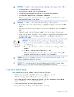
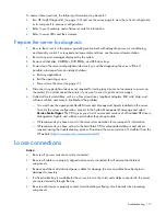
Страница 114: ...http www hp com support ProLiant_TSG_nl Japanese http www hp com support ProLiant_TSG_jp Pre diagnostic steps WARNING To avoid potential problems ALWAYS read the warnings and cautionary information in the server documentation before removing replacing reseating or modifying system components IMPORTANT This guide provides information for multiple servers Some information may not apply to the server...

Страница 115: ...s receptacle This symbol indicates the presence of a hot surface or hot component If this surface is contacted the potential for injury exists WARNING To reduce the risk of injury from a hot component allow the surface to cool before touching 49 109 kg 100 240 lb This symbol indicates that the component exceeds the recommended weight for one individual to handle safely WARNING To reduce the risk o...

Страница 116: ... 240 lb WARNING To reduce the risk of personal injury or damage to the equipment Observe local occupation health and safety requirements and guidelines for manual handling Obtain adequate assistance to lift and stabilize the chassis during installation or removal The server is unstable when not fastened to the rails When mounting the server in a rack remove the power supplies and any other removab...

Страница 117: ... a Torx screwdriver loopback adapters ESD wrist strap and software utilities necessary to troubleshoot the problem o You must have the appropriate Health Drivers and Management Agents installed on the server To verify the server configuration connect to the System Management homepage and select Version Control Agent The VCA gives you a list of names and versions of all installed HP drivers Managem...

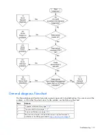
Страница 118: ...ic path If the other flowcharts do not provide a troubleshooting solution follow the diagnostic steps in General diagnosis flowchart on page 119 The General diagnosis flowchart is a generic troubleshooting process to be used when the problem is not server specific or is not easily categorized into the other flowcharts The available flowcharts include Start diagnosis flowchart on page 118 General d...

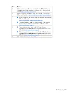
Страница 119: ...ure of the problem or if the other flowcharts do not fix the problem use the following flowchart Item Refer to 1 Symptom information on page 116 2 Loose connections on page 117 3 Service notifications on page 118 4 The most recent version of a particular server or option firmware is available on the HP Support website http www hp com support ...

Страница 120: ... the Documentation CD or the HP website http www hp com products servers platforms Hardware problems in the HP ProLiant Servers Troubleshooting Guide located on the Documentation CD or on the HP website http www hp com support 8 Server information you need in the HP ProLiant Servers Troubleshooting Guide located on the Documentation CD or on the HP website http www hp com support Operating system ...

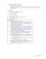
Страница 121: ...Troubleshooting 121 Server power on problems flowchart Symptoms The server does not power on The system power LED is off or amber ...

Страница 122: ...e and service guide located on the Documentation CD or the HP website http www hp com products servers platforms 5 Integrated Management Log on page 108 or in the HP ProLiant Servers Troubleshooting Guide located on the Documentation CD or on the HP website http www hp com support 6 Power source problems in the HP ProLiant Servers Troubleshooting Guide located on the Documentation CD or on the HP ...

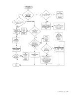
Страница 123: ...Troubleshooting 123 ...

Страница 124: ...rs platforms 7 Port 85 and iLO messages in the HP ProLiant Servers Troubleshooting Guide located on the Documentation CD or on the HP website http www hp com support 8 General memory problems are occurring in the HP ProLiant Servers Troubleshooting Guide located on the Documentation CD or on the HP website http www hp com support 9 Hardware problems in the HP ProLiant Servers Troubleshooting Guide...

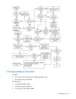
Страница 125: ...problems flowchart Symptoms Server does not boot a previously installed operating system Server does not boot SmartStart Possible causes Corrupted operating system Hard drive subsystem problem Incorrect boot order setting in RBSU ...

Страница 126: ...umentation CD or on the HP website http www hp com support Controller documentation Loose connections on page 117 6 General memory problems are occurring in the HP ProLiant Servers Troubleshooting Guide located on the Documentation CD or on the HP website http www hp com support 7 Operating system problems in the HP ProLiant Servers Troubleshooting Guide located on the Documentation CD or on the H...

Страница 127: ...ver fault indications flowchart Symptoms Server boots but a fault event is reported by Insight Management Agents on page 105 Server boots but the internal health LED external health LED or component health LED is red or amber ...

Страница 128: ...http www hp com support 3 Component identification on page 7 4 System Management Homepage https localhost 2381 5 Power on problems flowchart Server power on problems flowchart on page 121 6 Smart Array SCSI Diagnosis feature in the HP ProLiant Servers Troubleshooting Guide located on the Documentation CD or on the HP website http www hp com support Server maintenance and service guide located on t...

Страница 129: ...r messages in the HP ProLiant Servers Troubleshooting Guide located on the Documentation CD or on the HP website http www hp com support WARNING To avoid potential problems ALWAYS read the warnings and cautionary information in the server documentation before removing replacing reseating or modifying system components ...

Страница 130: ...ample personal computers The FCC requires devices in both classes to bear a label indicating the interference potential of the device as well as additional operating instructions for the user FCC rating label The FCC rating label on the device shows the classification A or B of the equipment Class B devices have an FCC logo or ID on the label Class A devices do not have an FCC logo or ID on the la...

Страница 131: ...es Operation is subject to the following two conditions 1 this device may not cause harmful interference and 2 this device must accept any interference received including interference that may cause undesired operation For questions regarding this product contact us by mail or telephone Hewlett Packard Company P O Box 692000 Mail Stop 530113 Houston Texas 77269 2000 1 800 HP INVENT 1 800 474 6836 ...

Страница 132: ...duct complies with the following EU Directives Low Voltage Directive 2006 95 EC EMC Directive 2004 108 EC Compliance with these directives implies conformity to applicable harmonized European standards European Norms which are listed on the EU Declaration of Conformity issued by Hewlett Packard for this product or product family This compliance is indicated by the following conformity marking plac...

Страница 133: ...lectrical and electronic equipment The separate collection and recycling of your waste equipment at the time of disposal will help to conserve natural resources and ensure that it is recycled in a manner that protects human health and the environment For more information about where you can drop off your waste equipment for recycling please contact your local city office your household waste dispo...

Страница 134: ...tion Do not try to open the module enclosure There are no user serviceable components inside Do not operate controls make adjustments or perform procedures to the laser device other than those specified herein Allow only HP Authorized Service technicians to repair the unit The Center for Devices and Radiological Health CDRH of the U S Food and Drug Administration implemented regulations for laser ...

Страница 135: ...r agents For more information about battery replacement or proper disposal contact an authorized reseller or an authorized service provider Taiwan battery recycling notice The Taiwan EPA requires dry battery manufacturing or importing firms in accordance with Article 15 of the Waste Disposal Act to indicate the recovery marks on the batteries used in sales giveaway or promotion Contact a qualified...

Страница 136: ...atic sensitive component or assembly Grounding methods to prevent electrostatic discharge Several methods are used for grounding Use one or more of the following methods when handling or installing electrostatic sensitive parts Use a wrist strap connected by a ground cord to a grounded workstation or computer chassis Wrist straps are flexible straps with a minimum of 1 megohm 10 percent resistance...

Страница 137: ... m 1 8 F per 1 000 ft to 3048 m 10 000 ft is applicable No direct sunlight allowed Storage maximum humidity of 95 is based on a maximum temperature of 45 C 113 F Altitude maximum for storage corresponds to a pressure minimum of 70 kPa Server specifications Specification Value Dimensions Rack model Height 17 48 cm 6 88 in Depth 69 93 cm 27 53 in Width 48 34 cm 19 03 in Tower model Height 47 04 cm 1...

Страница 138: ... hour 3530 at 120V AC input 4600 at 200V to 240V AC input Power supply output Rated steady state power 800 W at 100V AC input 900 W at 120V AC input 1200 W at 200V to 240V AC input Maximum peak power 800 W at 100V AC input 900 W at 120V AC input 1200 W at 200V to 240V AC input HP ProLiant 750 W Power Supply Specification Value Input requirements Rated input voltage 100 to 120 VAC 200 to 240 VAC Ra...

Страница 139: ...nts Rated input voltage 100 to 120 VAC 200 to 240 VAC Rated input frequency 50 Hz to 60 Hz Rated input current 5 5 A at 100 VAC 2 6 A at 200 VAC Rated input power 526 W at 100V AC input 505 W at 200V AC input BTUs per hour 1794 at 100V AC input 1725 at 200V AC input Power supply output Rated steady state power 460 W at 100V to 120V AC input 460 W at 200V to 240V AC input Maximum peak power 460 W a...

Страница 140: ... service is available 24 hours a day 7 days a week For continuous quality improvement calls may be recorded or monitored o If you have purchased a Care Pack service upgrade call 1 800 633 3600 For more information about Care Packs refer to the HP website http www hp com hps In other locations see the Contact HP worldwide in English webpage http welcome hp com country us en wwcontact html Customer ...

Страница 141: ...ciliter le remplacement des pièces défectueuses Si pendant la période de diagnostic HP ou ses partenaires ou mainteneurs agréés détermine que la réparation peut être effectuée à l aide d une pièce CSR HP vous l envoie directement Il existe deux catégories de pièces CSR Obligatoire Pièces pour lesquelles la réparation par le client est obligatoire Si vous demandez à HP de remplacer ces pièces les c...

Страница 142: ... di costo solo in alcune zone In caso di necessità si può richiedere l assistenza telefonica di un addetto del centro di supporto tecnico HP Nel materiale fornito con una parte di ricambio CSR HP specifica se il cliente deve restituire dei componenti Qualora sia richiesta la resa ad HP del componente difettoso lo si deve spedire ad HP entro un determinato periodo di tempo generalmente cinque 5 gio...

Страница 143: ...res o socios de servicio de HP identifica que una reparación puede llevarse a cabo mediante el uso de un componente CSR HP le enviará dicho componente directamente para que realice su sustitución Los componentes CSR se clasifican en dos categorías Obligatorio componentes para los que la reparación por parte del usuario es obligatoria Si solicita a HP que realice la sustitución de estos componentes...

Страница 144: ...t onderdeel door een geautoriseerde Service Partner worden vervangen Deze onderdelen worden in de geïllustreerde onderdelencatalogus aangemerkt met Nee Afhankelijk van de leverbaarheid en de locatie worden CSR onderdelen verzonden voor levering op de eerstvolgende werkdag Levering op dezelfde dag of binnen vier uur kan tegen meerkosten worden aangeboden indien dit mogelijk is gezien de locatie Ind...

Страница 145: ...ido Onde as condições geográficas permitirem a entrega no mesmo dia ou em quatro horas pode ser feita mediante uma taxa adicional Se precisar de auxílio entre em contato com o Centro de suporte técnico da HP para que um técnico o ajude por telefone A HP especifica nos materiais fornecidos com a peça CSR de reposição se a peça com defeito deve ser devolvida à HP Nos casos em que isso for necessário...

Страница 146: ...Technical support 146 ...

Страница 147: ...Technical support 147 ...

Страница 148: ... AMP Advanced Memory Protection ASR Automatic Server Recovery BBWC battery backed write cache CSA Canadian Standards Association CSR Customer Self Repair DDR double data rate ECC error checking and correcting IEC International Electrotechnical Commission iLO Integrated Lights Out IML Integrated Management Log ...

Страница 149: ...OM Configuration for Arrays PCI peripheral component interface PCIe peripheral component interconnect express POST Power On Self Test PPM processor power module PSP ProLiant Support Pack RBSU ROM Based Setup Utility RDIMM Registered Dual In line Memory Module RDP Rapid Deployment Pack SAS serial attached SCSI SDRAM synchronous dynamic RAM ...

Страница 150: ...r Migration Pack SMTP Simple Mail Transfer Protocol SNMP Simple Network Management Protocol TMRA recommended ambient operating temperature UDIMM Unregistered Dual In Line Memory Module UID unit identification UPS uninterruptible power system USB universal serial bus VCA Version Control Agent ...

Страница 151: ...n problems 117 connectors 7 contacting HP 140 crash dump analysis 15 D Declaration of Conformity 131 deployment software 102 device numbers 15 diagnosing problems 114 diagnostic tools 99 102 103 108 diagnostics utility 108 DIMM identification 45 DIMM installation guidelines 47 DIMM population guidelines 47 DIMM slots 13 18 47 DIMMs 43 44 disposal waste 132 downloading files 140 drive cage jumper 2...

Страница 152: ...ortant Safety Information document 114 Insight Control Environment Suites 106 Insight Diagnostics 108 109 installation services 30 installing operating system 37 Integrated Lights Out iLO 104 Integrated Management Log IML 108 internal cables 93 J Japanese notice 133 jumpers 21 K keyboard connector 11 L laser devices 134 LEDs 7 8 9 12 LEDs hard drive 17 LFF backplane 60 link LED 12 loose connection...

Страница 153: ...s 32 SmartStart autorun menu 99 SmartStart Scripting Toolkit 99 SmartStart software 37 software 99 space requirements 31 specifications server 137 static electricity 136 storage controller 78 StorageWorks Library and Tape Tools L TT 104 support packs 99 switches 15 symbols on equipment 115 system board battery 134 system board components 13 system components 7 system configuration settings 37 99 s...

Отзывы: