


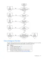


Troubleshooting 115
Important safety information
Before servicing this product, read the
Important Safety Information
document provided with the server.
Symbols on equipment
The following symbols may be placed on equipment to indicate the presence of potentially hazardous
conditions.
This symbol indicates the presence of hazardous energy circuits or electric shock
hazards. Refer all servicing to qualified personnel.
WARNING:
To reduce the risk of injury from electric shock hazards, do not open this
enclosure. Refer all maintenance, upgrades, and servicing to qualified personnel.
This symbol indicates the presence of electric shock hazards. The area contains no
user or field serviceable parts. Do not open for any reason.
WARNING:
To reduce the risk of injury from electric shock hazards, do not open this
enclosure.
This symbol on an RJ-45 receptacle indicates a network interface connection.
WARNING:
To reduce the risk of electric shock, fire, or damage to the equipment,
do not plug telephone or telecommunications connectors into this receptacle.
This symbol indicates the presence of a hot surface or hot component. If this surface is
contacted, the potential for injury exists.
WARNING:
To reduce the risk of injury from a hot component, allow the surface to
cool before touching.
49-109 kg
100-240 lb
This symbol indicates that the component exceeds the recommended weight for one
individual to handle safely.
WARNING:
To reduce the risk of personal injury or damage to the equipment,
observe local occupational health and safety requirements and guidelines for manual
material handling.
These symbols, on power supplies or systems, indicate that the equipment is supplied
by multiple sources of power.
WARNING:
To reduce the risk of injury from electric shock, remove all power cords
to completely disconnect power from the system.
Warnings and cautions
WARNING:
Only authorized technicians trained by HP should attempt to repair this
equipment. All troubleshooting and repair procedures are detailed to allow only
subassembly/module-level repair. Because of the complexity of the individual boards and
subassemblies, no one should attempt to make repairs at the component level or to make
modifications to any printed wiring board. Improper repairs can create a safety hazard.
Содержание ProLiant DL370
Страница 1: ...HP ProLiant DL ML370 G6 Server User Guide Part Number 513482 001 March 2009 First Edition ...
Страница 16: ...Component identification 16 SFF hard drives LFF hard drives ...
Страница 29: ...Operations 29 6 Remove the hard drive cage blank ...
Страница 83: ...Hardware options installation 83 o Rear 1 o Front 2 17 Remove the chassis from the tower side panels ...
Страница 94: ...Cabling 94 Drive cage bay 2 Drive cage bay 3 ...
Страница 95: ...Cabling 95 Six bay LFF backplane cabling Drive cage bay 1 Drive cage bay 2 ...
Страница 97: ...Cabling 97 Battery cabling for BBWC DVD ROM drive cabling ...
Страница 98: ...Cabling 98 Slimline optical drive cabling ...
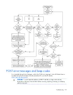
Страница 123: ...Troubleshooting 123 ...
Страница 146: ...Technical support 146 ...
Страница 147: ...Technical support 147 ...