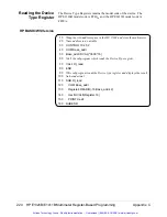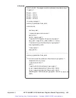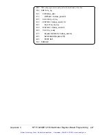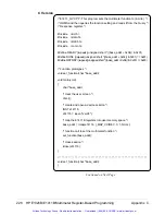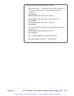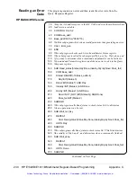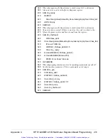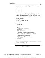
Register Triggering
This section reviews the multimeter’s trigger system from the register-based
standpoint. The section shows the triggering models used by the burst and
scanning measurement examples in the “Programming Examples” section.
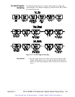
Also shown is the triggering model used for Control Register sampling.
The Trigger System
The operation of the multimeter trigger system is shown in Figure C-9.
Comments
•
The multimeter is configured while it is in the Idle state.
•
When the Trigger Source is Hold, Trigger Arm moves the
multimeter from the Idle state to the Wait-for-trigger state. Trigger
Immediate or a trigger from another source moves the multimeter to
the Triggered state. The measurement that is taken is appended to
the other readings in the buffer.
•
When the Trigger Source is Immediate, Trigger Arm moves the
multimeter directly to the Triggered State. The measurement
overwrites any data currently in the data buffer.
•
The multimeter returns to the Wait-for-trigger state once the number
of measurements equals the specified sample count.
•
The multimeter returns to the Idle state when any of the following
occurs:
–
the number of triggers received equals the specified trigger count
–
the multimeter is disarmed
–
the multimeter configuration is changed
–
there is a reading overrun (the buffer fills)
Figure C-9. Multimeter Trigger System
Appendix C
HP E1326B/E1411B Multimeter Register-Based Programming 217
Artisan Technology Group - Quality Instrumentation ... Guaranteed | (888) 88-SOURCE | www.artisantg.com


