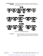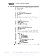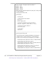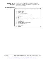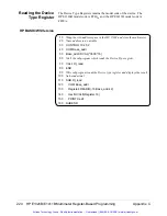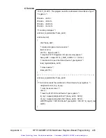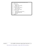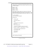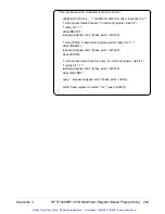
Checking for Errors
Error conditions are monitored and error codes are returned as indicated in
figure C-6.
Comments
•
The registers used are:
–
Status Register (base + 04
16
)
–
Command Register (base + 08
16
)
–
Query Response Register (base + 08
16
)
•
Status Register bit 7 is monitored to determine when the previous
command has finished. Bit 6 is monitored to determine when a
configuration error has occurred.
•
Once an error is detected, the error code is written to the Query
Response Register with the Send Error command (opcode 15).
•
Status Register bit 1 is monitored to determine when the error code
can be read from the Query Response Register.
Figure C-6. Checking for Errors
214 HP E1326B/E1411B Multimeter Register-Based Programming
Appendix C
Artisan Technology Group - Quality Instrumentation ... Guaranteed | (888) 88-SOURCE | www.artisantg.com


