5–40
Maintenance and Service Guide
Removal and Replacement Procedures
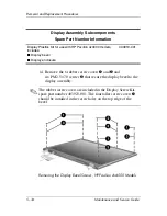
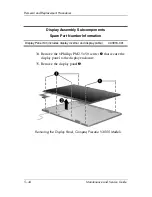
26. Remove the 6 rubber screw covers
1
and
2
and
six PM2.5×7.0 screws
3
that secure the display bezel to the
display assembly.
✎
The rubber screw covers are included in the Display Screw Kit,
spare part number 403924-001. The four taller screw covers
1
should be installed in the screw holes on the top edge of the
bezel.
Removing the Display Bezel Screws, Compaq Presario V4000
Models
Display Assembly Subcomponents
Spare Part Number Information
Display Plastics Kit for use with Compaq Presario V4000
models, includes:
■
Display bezel
■
Display enclosure
■
Display hinge covers)
403920-001
Содержание Compaq Presario V400
Страница 62: ...3 4 Maintenance and Service Guide Illustrated Parts Catalog Notebook Major Components Compaq Presario V4000 ...
Страница 64: ...3 6 Maintenance and Service Guide Illustrated Parts Catalog Notebook Major Components HP Pavilion dv4000 ...
Страница 66: ...3 8 Maintenance and Service Guide Illustrated Parts Catalog Notebook Major Components Compaq Presario V4000 ...
Страница 68: ...3 10 Maintenance and Service Guide Illustrated Parts Catalog Notebook Major Components HP Pavilion dv4000 ...
Страница 76: ...3 18 Maintenance and Service Guide Illustrated Parts Catalog 3 7 Mass Storage Devices ...
Страница 107: ...Removal and Replacement Procedures Maintenance and Service Guide 5 11 Replacing the Notebook Feet Compaq Presario V4000 ...
Страница 247: ...D 14 Maintenance and Service Guide Display Component Recycling 23 Remove the LCD panel Removing the LCD Panel ...

