5–70
Maintenance and Service Guide
Removal and Replacement Procedures
5.19 Fan Assembly
✎
The fan assembly is included in the heat sink assembly spare
part kit, spare part number 384622-001. Refer to refer
Section
5.10, “Heat Sink,”
for information on removing the heat sink.)
1. Prepare the notebook for disassembly (
Section 5.3
)
and remove the following components:
a. Hard drive (
Section 5.4
)
b. Switch cover (
Section 5.12
)
c. Keyboard (
Section 5.13
)
d. Display assembly (
Section 5.14
)
e. Top cover (
Section 5.15
)
f. System board (
Section 5.18
)
2. Turn the system board upside down with the right side
toward you.
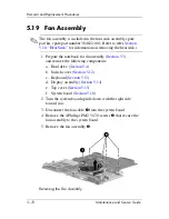
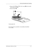
3. Disconnect the fan cable
1
from the system board.
4. Remove the 4 Phillips PM2.5×7.0 screws
2
that secure the
fan assembly to the system board.
5. Remove the fan assembly
3
.
Removing the Fan Assembly
Содержание Compaq Presario V400
Страница 62: ...3 4 Maintenance and Service Guide Illustrated Parts Catalog Notebook Major Components Compaq Presario V4000 ...
Страница 64: ...3 6 Maintenance and Service Guide Illustrated Parts Catalog Notebook Major Components HP Pavilion dv4000 ...
Страница 66: ...3 8 Maintenance and Service Guide Illustrated Parts Catalog Notebook Major Components Compaq Presario V4000 ...
Страница 68: ...3 10 Maintenance and Service Guide Illustrated Parts Catalog Notebook Major Components HP Pavilion dv4000 ...
Страница 76: ...3 18 Maintenance and Service Guide Illustrated Parts Catalog 3 7 Mass Storage Devices ...
Страница 107: ...Removal and Replacement Procedures Maintenance and Service Guide 5 11 Replacing the Notebook Feet Compaq Presario V4000 ...
Страница 247: ...D 14 Maintenance and Service Guide Display Component Recycling 23 Remove the LCD panel Removing the LCD Panel ...

