6-57
Removal and Replacement
PINCH ARM AND LIFT MECHANISM REMOVAL
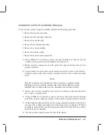
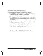
To remove the pinch arm lift mechanism, perform the following procedure:
1. Remove the window assembly.
2. Remove the left and right endcovers.
3. Remove the encoder strip.
4. Remove the bail assembly.
5. Remove the overdrive support assembly.
6. Remove the drive roller assembly.
7. Place the manual lift lever in the “down” position.
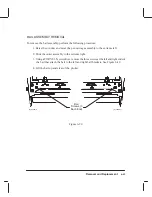
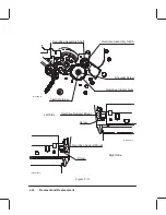
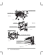
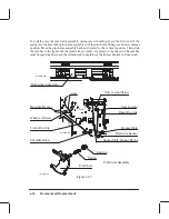
8. Disconnect the rocker plate tension spring to relieve any remaining tension on the
pinch arm lift mechanism. See Figure 6-37.
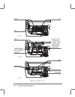
9. On the right side, use a TORX T-9 screwdriver to turn the cam journal screw 12 turns
counter-clockwise and push the screw in toward the center of the plotter. Repeat this
step again and try to pull the cam journal and rear wire link to the right and clear of
the cam lift bar. If unsuccessful, turn the cam journal screw two more turns counter-
clockwise, push the screw in toward the center of the plotter, and try again to pull the
cam journal and rear wire link to the right and clear of the cam lift bar. Repeat the last
two actions until successful.
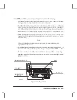
10. Grasping the cam journal on the left side with your left hand, reach around to the
front of the plotter and push the top of the cam lift bar slightly toward the rear of the
plotter and simultaneously pull the cam journal to the left. The cam lift bar will begin
to slide out of the chassis on the left side.
11. Slide the cam lift bar about three inches out of the chassis with your left hand. Press-
ing the right-most pinch arm assembly toward the rear of the plotter against its
spring tension with your right hand, slide the cam lift bar left until it clears that pinch
arm assembly. Then remove the pinch arm assembly and spring from the chassis by
rotating it 90 degrees clockwise. Take care that the spring does not fall.
12. Press the next right-most pinch arm assembly toward the rear of the plotter against
its spring tension and slide the cam lift bar left until it clears that pinch arm assembly.
Then remove the pinch arm assembly and spring from the chassis. Repeat this step
until all of the pinch arm assemblies have been removed or until you have removed
the pinch arm assembly that is to be replaced.
Содержание C2858A
Страница 125: ...7 10 Adjustments Calibrations Notes ...
Страница 155: ...9 4 Product History Notes ...
Страница 160: ...10 5 Parts and Diagrams Illustrated Parts Breakdown Stand Assemblies 1 2 3 4 5 6 7 8 1 3 5 3 3 3 3 3 9 9 C C2858 1 1 ...
Страница 164: ...10 9 Parts and Diagrams Illustrated Parts Breakdown C2859A Electronics Enclosure C C2858 3 1 ...
Страница 166: ...10 11 Parts and Diagrams Illustrated Parts Breakdown C2858A Electronics Enclosure C C2858 4 1 ...
Страница 176: ...10 21 Parts and Diagrams Illustrated Parts Breakdown Service Station Assembly 1 2 3 4 5 6 C C2858 9 1 7 8 9 10 11 12 ...
Страница 180: ...10 25 Parts and Diagrams 1 3 Illustrated Parts Breakdown Pen Carriage Assembly 6 C C2858 11 1 5 7 2 8 9 2 4 5 10 ...
Страница 182: ...10 27 Parts and Diagrams Illustrated Parts Breakdown Paper Drive Assemblies C C2858 12 1 ...
Страница 184: ...10 29 Parts and Diagrams Illustrated Parts Breakdown Bail and Overdrive Support Assemblies C C2858 13 1 ...
Страница 188: ...10 33 Parts and Diagrams Illustrated Parts Breakdown Starwheel Starguard and Chassis Assemblies C C2858 15 1 ...
Страница 198: ... ...

