Chapter 6
Removal and Replacement
6-1
Removal and Replacement
INTRODUCTION
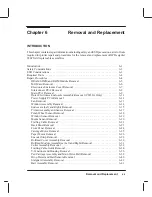
This chapter contains repair information including safety and ESD precautions, a list of tools
required for plotter repair and procedures for the removal and replacement of HP DesignJet
650C field replaceable assemblies.
Introduction
6-1
. . . . . . . . . . . . . . . . . . . . . . . . . . . . . . . . . . . . . . . . . . . . . . . . . . . . . . .
Safety Considerations
6-3
. . . . . . . . . . . . . . . . . . . . . . . . . . . . . . . . . . . . . . . . . . . . . . .
ESD Considerations
6-3
. . . . . . . . . . . . . . . . . . . . . . . . . . . . . . . . . . . . . . . . . . . . . . . . .
Required Tools
6-4
. . . . . . . . . . . . . . . . . . . . . . . . . . . . . . . . . . . . . . . . . . . . . . . . . . . . .
Repair Procedures
6-4
. . . . . . . . . . . . . . . . . . . . . . . . . . . . . . . . . . . . . . . . . . . . . . . . . .
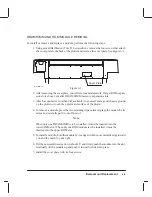
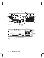
DRAM SIMM and ROM Module Removal
6-5
. . . . . . . . . . . . . . . . . . . . . . . . . . .
MIO Card Removal
6-6
. . . . . . . . . . . . . . . . . . . . . . . . . . . . . . . . . . . . . . . . . . . . . .
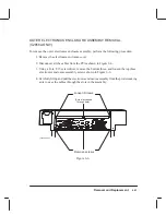
Electronics Enclosure Cover Removal
6-7
. . . . . . . . . . . . . . . . . . . . . . . . . . . . . . .
Interconnect PCA Removal
6-8
. . . . . . . . . . . . . . . . . . . . . . . . . . . . . . . . . . . . . . . .
Main PCA Removal
6-9
. . . . . . . . . . . . . . . . . . . . . . . . . . . . . . . . . . . . . . . . . . . . .
Outer Electronics Enclosure Assembly Removal (C2858A Only)
6-11
. . . . . . . . . .
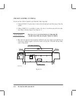
Power Supply PCA Removal
6-12
. . . . . . . . . . . . . . . . . . . . . . . . . . . . . . . . . . . . . .
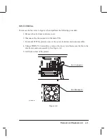
Fan Removal
6-13
. . . . . . . . . . . . . . . . . . . . . . . . . . . . . . . . . . . . . . . . . . . . . . . . . . .
Window Assembly Removal
6-14
. . . . . . . . . . . . . . . . . . . . . . . . . . . . . . . . . . . . . . .
Endcovers (Left and Right) Removal
6-15
. . . . . . . . . . . . . . . . . . . . . . . . . . . . . . . .
Primer Assembly and Sensor Removal
6-17
. . . . . . . . . . . . . . . . . . . . . . . . . . . . . . .
Pinch Wheel Sensor Removal
6-18
. . . . . . . . . . . . . . . . . . . . . . . . . . . . . . . . . . . . . .
Window Sensor Removal
6-19
. . . . . . . . . . . . . . . . . . . . . . . . . . . . . . . . . . . . . . . . .
Media Sensor Removal
6-20
. . . . . . . . . . . . . . . . . . . . . . . . . . . . . . . . . . . . . . . . . . .
Trailing Cable Removal
6-21
. . . . . . . . . . . . . . . . . . . . . . . . . . . . . . . . . . . . . . . . . .
Back Panel Removal
6-23
. . . . . . . . . . . . . . . . . . . . . . . . . . . . . . . . . . . . . . . . . . . . .
Front Panel Removal
6-24
. . . . . . . . . . . . . . . . . . . . . . . . . . . . . . . . . . . . . . . . . . . . .
Carriage Motor Removal
6-25
. . . . . . . . . . . . . . . . . . . . . . . . . . . . . . . . . . . . . . . . . .
Paper Motor Removal
6-26
. . . . . . . . . . . . . . . . . . . . . . . . . . . . . . . . . . . . . . . . . . . .
Encoder Strip Removal
6-28
. . . . . . . . . . . . . . . . . . . . . . . . . . . . . . . . . . . . . . . . . . .
Rollfeed Cover Assembly Removal
6-30
. . . . . . . . . . . . . . . . . . . . . . . . . . . . . . . . .
Rollfeed Module Assemblies (Left and Right) Removal
6-31
. . . . . . . . . . . . . . . . .
Cutter Assembly Removal
6-32
. . . . . . . . . . . . . . . . . . . . . . . . . . . . . . . . . . . . . . . .
Trailing Cable Guide Removal
6-34
. . . . . . . . . . . . . . . . . . . . . . . . . . . . . . . . . . . . .
Y-Tensioner and Housing Removal
6-36
. . . . . . . . . . . . . . . . . . . . . . . . . . . . . . . . . .
Pen Carriage Assembly and Main Drive Belt Removal
6-38
. . . . . . . . . . . . . . . . . .
Drop Detect and Bail Sensors Removal
6-40
. . . . . . . . . . . . . . . . . . . . . . . . . . . . . .
Starguard Assembly Removal
6-42
. . . . . . . . . . . . . . . . . . . . . . . . . . . . . . . . . . . . . .
Bail Assembly Removal
6-43
. . . . . . . . . . . . . . . . . . . . . . . . . . . . . . . . . . . . . . . . . .
Содержание C2858A
Страница 125: ...7 10 Adjustments Calibrations Notes ...
Страница 155: ...9 4 Product History Notes ...
Страница 160: ...10 5 Parts and Diagrams Illustrated Parts Breakdown Stand Assemblies 1 2 3 4 5 6 7 8 1 3 5 3 3 3 3 3 9 9 C C2858 1 1 ...
Страница 164: ...10 9 Parts and Diagrams Illustrated Parts Breakdown C2859A Electronics Enclosure C C2858 3 1 ...
Страница 166: ...10 11 Parts and Diagrams Illustrated Parts Breakdown C2858A Electronics Enclosure C C2858 4 1 ...
Страница 176: ...10 21 Parts and Diagrams Illustrated Parts Breakdown Service Station Assembly 1 2 3 4 5 6 C C2858 9 1 7 8 9 10 11 12 ...
Страница 180: ...10 25 Parts and Diagrams 1 3 Illustrated Parts Breakdown Pen Carriage Assembly 6 C C2858 11 1 5 7 2 8 9 2 4 5 10 ...
Страница 182: ...10 27 Parts and Diagrams Illustrated Parts Breakdown Paper Drive Assemblies C C2858 12 1 ...
Страница 184: ...10 29 Parts and Diagrams Illustrated Parts Breakdown Bail and Overdrive Support Assemblies C C2858 13 1 ...
Страница 188: ...10 33 Parts and Diagrams Illustrated Parts Breakdown Starwheel Starguard and Chassis Assemblies C C2858 15 1 ...
Страница 198: ... ...

