8-3
Troubleshooting
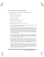
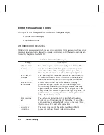
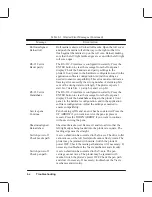
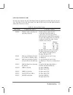
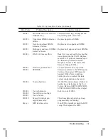
a. The EEROM checksum is tested. If this portion of the test fails, clearorreĆ
place the EEROM and run the calibration adjustments described in chapter
7. If replacing the EEROM and running the adjustments does not fix the
problem, replace the main PCA.
b. The servo processor transfer buffer and interrupt tracking abilities are tested.
If this test fails, replace the main PCA.
c. Another communication test between the processors is performed. Check the
trailing cable and connect or replace it. If these actions do not fix the probĆ
lem, replace the main PCA and rerun the tests. If replacing the main PCA
does not fix the problem, replace the carriage assembly.
d. The carriage ASIC is tested. If this test fails, replace the carriage assembly. If
all tests pass, fourdots ...." will be displayed, and the mechanical initializaĆ
tion will begin.
MECHANICAL INITIALIZATION
During mechanical initialization, the following tests are performed:
1. The window sensor is checked. The initialization will not continue unless the win-
dow is in the “down” position.
2. The bail sensor is checked and the pen primer assembly is initialized.
3. The Y-axis is initialized. First the left stop is found, then the right (contact with the
cutter is made). The carriage then parks in the service station.
4. The pinch wheel position sensor is checked. If the optical sensor does not see light,
the plotter will act as if the pinch wheel lift lever is UP.
5. The media sensor is checked. If the optical sensor does not see light, the plotter will
act as if media is already present. A bad sensor could cause the plotter to try to load
media with media present or drop media out of the plotter during the rear edge search
(if sheet media is loaded at power ON). After the mechanical initialization is com-
plete, the plotter is placed into a ready state (either to accept media or to plot).
6. X-axis feedback operation is checked.
7. Remainder of DRAM tested.
Содержание C2858A
Страница 125: ...7 10 Adjustments Calibrations Notes ...
Страница 155: ...9 4 Product History Notes ...
Страница 160: ...10 5 Parts and Diagrams Illustrated Parts Breakdown Stand Assemblies 1 2 3 4 5 6 7 8 1 3 5 3 3 3 3 3 9 9 C C2858 1 1 ...
Страница 164: ...10 9 Parts and Diagrams Illustrated Parts Breakdown C2859A Electronics Enclosure C C2858 3 1 ...
Страница 166: ...10 11 Parts and Diagrams Illustrated Parts Breakdown C2858A Electronics Enclosure C C2858 4 1 ...
Страница 176: ...10 21 Parts and Diagrams Illustrated Parts Breakdown Service Station Assembly 1 2 3 4 5 6 C C2858 9 1 7 8 9 10 11 12 ...
Страница 180: ...10 25 Parts and Diagrams 1 3 Illustrated Parts Breakdown Pen Carriage Assembly 6 C C2858 11 1 5 7 2 8 9 2 4 5 10 ...
Страница 182: ...10 27 Parts and Diagrams Illustrated Parts Breakdown Paper Drive Assemblies C C2858 12 1 ...
Страница 184: ...10 29 Parts and Diagrams Illustrated Parts Breakdown Bail and Overdrive Support Assemblies C C2858 13 1 ...
Страница 188: ...10 33 Parts and Diagrams Illustrated Parts Breakdown Starwheel Starguard and Chassis Assemblies C C2858 15 1 ...
Страница 198: ... ...

