5-6
Functional Overview
CARRIAGE PCA
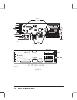
The carriage PCA contains an application-specific, integrated circuit (ASIC) that controls
the operation of the pens and pen drivers that switch power pulses from the ASIC to fire the
pens. It also provides feedback to the main PCA as to the current position of the carriage as-
sembly. A line sensor module mounted on the carriage PCA monitors the lines produced by
the pens and is used for pen alignment. The line sensor also provides an edge sensing capabil-
ity used to identify the media loaded in the plotter. Voltage sense circuitry senses deviations
in the pen voltages supplied to the print heads and sends signals to the voltage regulators on
the interconnect PCA.
The carriage processor and the print control ASIC on the carriage PCA are driven by a 12.288
MHz, on-board clock. At power-on time, the main PCA reset circuit delays the operation of
the print control ASIC until the +5 V reaches a steady state.
The line sensor module is used to calibrate the writing system for mechanical tolerances as
well as to sense the left and right edges of the media. It consists of a photo-diode device
whose photo-current is amplified by a transimpedance amplifier connected to the PCA
through a ZIF connector. The resulting voltages are coupled and then measured by an eight-
bit, analog–to–digital (A/D) converter whose bits are sent serially to the carriage micropro-
cessor. Illumination of the surface being read by the line sensor is provided by two green,
high-intensity LEDs. A dual lens, unity conjugate ratio system directs the light from the illu-
minated surface to the sensor-phase plate combination.
A temperature sensor IC is used to measure ambient temperature near the print heads. Energy
used to fire the pens is based on temperature. This temperature reading is also used to deter-
mine when to switch the fan ON. Normally, the fan only runs when plotting. At high tempera-
tures, it is left ON.
A linear encoder detects pen carriage position as the carriage assembly moves along the en-
coder strip. The linear encoder IC is connected to the carriage PCA via a 5-pin ZIF connector.
The carriage processor operates at 12.288 MHz. The clock signal is generated by a crystal-
oscillator circuit internal to the ASIC. The primary task of the processor is to configure the
print control ASIC and read data to control pen energy and pen calibration. It communicates
with the servo processor on the main PCA using a serial port.
The print control (carriage) ASIC receives pixel data from the processor support ASIC on the
main PCA via a synchronous serial channel and on–board line driver. Signals from the print
control ASIC fire the nozzles in the print heads. Whenever a print head nozzle is fired, a com-
parator outputs a pulse to a counter in the carriage microprocessor.
Содержание C2858A
Страница 125: ...7 10 Adjustments Calibrations Notes ...
Страница 155: ...9 4 Product History Notes ...
Страница 160: ...10 5 Parts and Diagrams Illustrated Parts Breakdown Stand Assemblies 1 2 3 4 5 6 7 8 1 3 5 3 3 3 3 3 9 9 C C2858 1 1 ...
Страница 164: ...10 9 Parts and Diagrams Illustrated Parts Breakdown C2859A Electronics Enclosure C C2858 3 1 ...
Страница 166: ...10 11 Parts and Diagrams Illustrated Parts Breakdown C2858A Electronics Enclosure C C2858 4 1 ...
Страница 176: ...10 21 Parts and Diagrams Illustrated Parts Breakdown Service Station Assembly 1 2 3 4 5 6 C C2858 9 1 7 8 9 10 11 12 ...
Страница 180: ...10 25 Parts and Diagrams 1 3 Illustrated Parts Breakdown Pen Carriage Assembly 6 C C2858 11 1 5 7 2 8 9 2 4 5 10 ...
Страница 182: ...10 27 Parts and Diagrams Illustrated Parts Breakdown Paper Drive Assemblies C C2858 12 1 ...
Страница 184: ...10 29 Parts and Diagrams Illustrated Parts Breakdown Bail and Overdrive Support Assemblies C C2858 13 1 ...
Страница 188: ...10 33 Parts and Diagrams Illustrated Parts Breakdown Starwheel Starguard and Chassis Assemblies C C2858 15 1 ...
Страница 198: ... ...

