statements, or you
can
use AGL statements which the computer encodes
and sends
to
the plotter as HP-GL instructions. The Interfacing and
Programming
Manual contains complete infonnation about handshak·
ing and programming in HP·GL.
Introduction to the Plotter Coordinate
System
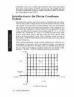
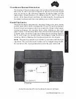
The plotter area is that area of the paper in which the pen can draw.
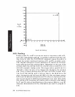
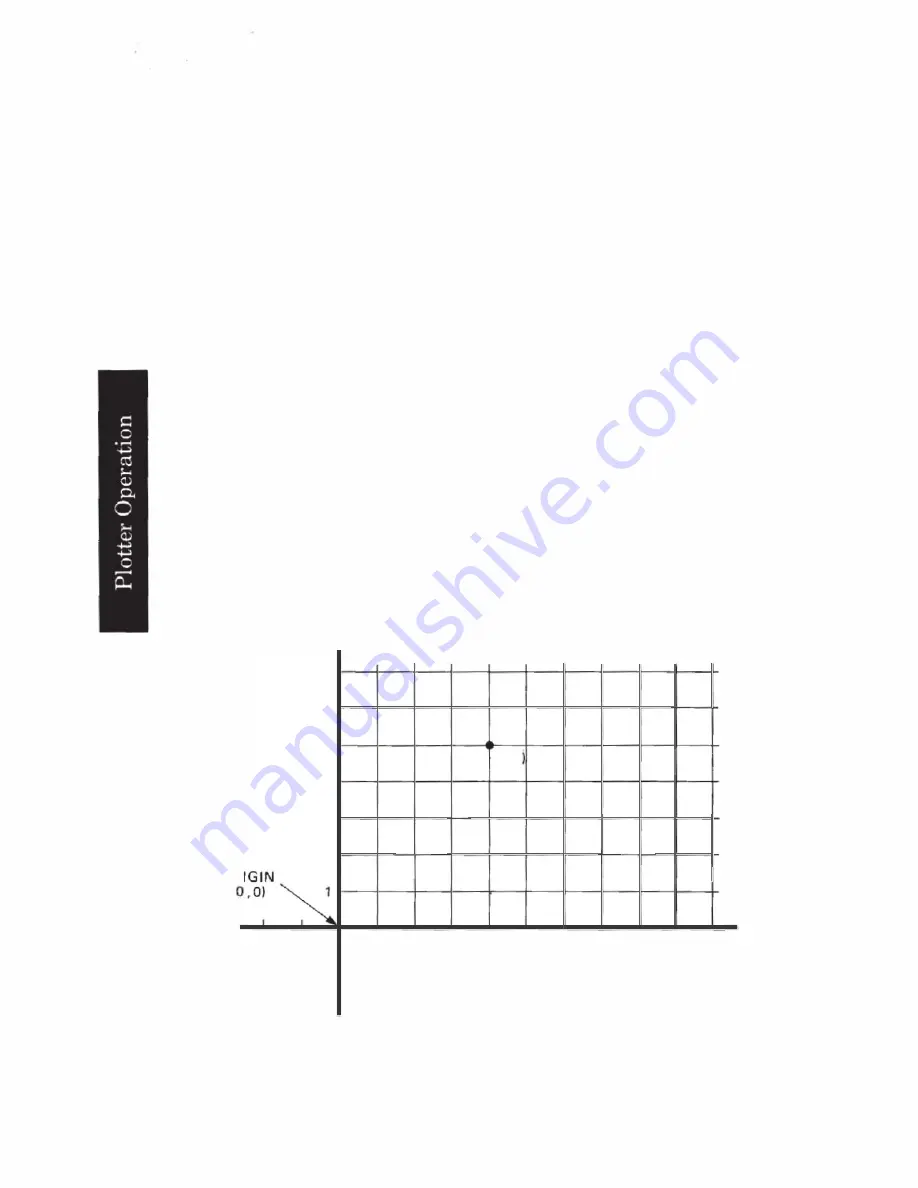
This area should be thought of as a two-dimensional Cartesian coordi·
nate system. In this system, the entire plotting area is divided (scaled)
into a grid as shown in the following illustration. Each intersection of
these grid lines represents a distinct point that is expressed by X-and
Y·axis coordinates with respect
to
the origin point (X
=
0,
Y
=
0). For
example, the coordinates X
=
4 and Y
=
5
define the point at the inter
section of the fourth positive grid line along the X-axis and the fifth
positive grid line along the Y·axis. These coordinate values are used as
parameters in HP-GL instructions to move the pen to any given point
in the plotting area.
Grid spacing (resolution) can be in either plotter units, which have a
fixed length, or user units, which are variable in length. A plotter unit
is 0. 02488 mm ( 0. 000
98
in.) in length and is the smallest move the plot
ter can make. The maximum numeric range that the plotter under·
stands
is
-32768
to
+32767 for both plotter units and user units.
+32767
•
•
7
6
y
·AXIS
5
4
3
2
OR
I
-32768
••
•
-2
-1
-1
-2
•
•
-32768
2·4
'
P
L
O'ITER OPERATION
14,5
1
2
3
4
5
6
7
B
9
10' •
•
+32767
X-AXIS
Cartesian Coordinates
Содержание 7475a
Страница 1: ... FliOW HEWLETT PACKARD HP 7475A Graphics Plotter ...
Страница 2: ...OPERATION HP 7475A AND Graphics Plotter INTERCONNECTION MANUAL ...
Страница 8: ...f i oil I V J ...
Страница 18: ......
Страница 51: ...NOTES ...
Страница 52: ......
Страница 80: ......
Страница 86: ...NOTES ...
Страница 100: ...NOTES ...


