Using this Manual
iv
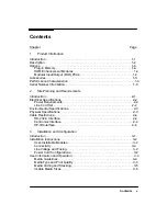
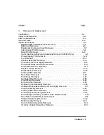
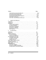
Chapter 4. Preventive Maintenance
Chapter 4 contains information you will need to keep the plotters in their
best operating condition. Included are procedures that can be performed by
the user.
Chapter 5. Functional Overview
This chapter contains a simplified description of the plotter circuits and
mechanical functions.
Chapter 6. Removal and Replacement
Procedures for the removal and replacement of field replaceable units are
provided in this chapter along with electrostatic discharge information and
recommended tools to perform repairs.
Chapter 7. Adjustments
Here you will find descriptions of any adjustments and calibrations that may
be required to return the plotter to proper operating condition.
Chapter 8. Troubleshooting
Included in Chapter 8 are service tests, error codes and messages, and
diagnostic information to assist you in troubleshooting and solving plotter
symptoms and failures.
Chapter 9. Product History
Chapter 9 provides historical tracking of changes made to the plotters. The
differences between earlier versions of the plotters and the version
described in the main body of this manual are identified.
Chapter 10. Parts and Diagrams
In this chapter you will find drawings for purposes of identifying the various
field replaceable assemblies. Also in this chapter are associated parts lists
for ordering replacement parts shown on the drawings.
Glossary
The glossary contains a listing of terms used throughout the manual.
Index
Use the index to find references and locate subject matter in this manual.
Содержание 650c - DesignJet Color Inkjet Printer
Страница 1: ...PrinterFAQ COM HP DesignJet650C User Guide ...
Страница 126: ...7 10 Adjustments Calibrations Notes ...
Страница 156: ...9 4 Product History Notes ...
Страница 161: ...10 5 Parts and Diagrams Illustrated Parts Breakdown Stand Assemblies 1 2 3 4 5 6 7 8 1 3 5 3 3 3 3 3 9 9 C C2858 1 1 ...
Страница 165: ...10 9 Parts and Diagrams Illustrated Parts Breakdown C2859A Electronics Enclosure C C2858 3 1 ...
Страница 167: ...10 11 Parts and Diagrams Illustrated Parts Breakdown C2858A Electronics Enclosure C C2858 4 1 ...
Страница 177: ...10 21 Parts and Diagrams Illustrated Parts Breakdown Service Station Assembly 1 2 3 4 5 6 C C2858 9 1 7 8 9 10 11 12 ...
Страница 181: ...10 25 Parts and Diagrams 1 3 Illustrated Parts Breakdown 5 6 Pen Carriage Assembly C C2858 11 1 7 2 8 9 2 4 5 10 ...
Страница 183: ...10 27 Parts and Diagrams Illustrated Parts Breakdown Paper Drive Assemblies C C2858 12 1 ...
Страница 185: ...10 29 Parts and Diagrams Illustrated Parts Breakdown Bail and Overdrive Support Assemblies C C2858 13 1 ...
Страница 189: ...10 33 Parts and Diagrams Illustrated Parts Breakdown Starwheel Starguard and Chassis Assemblies C C2858 15 1 ...
Страница 199: ......


