background image

Programming Function Blocks and Features  


Video Recorder – User Manual 


83

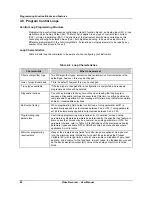
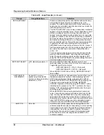
4.5 Set Mode 

Select this item to change the operating mode of the instrument to Online, Program or Maintenance.  
The top of the display will show which mode you have changed to. 

Program mode 

Program mode is an off-line mode for programming (configuring) the instrument.  In this mode, all 
outputs are frozen. 

Online mode 

Online Mode enables full use of the instrument with its inputs, outputs and internal programming. In this 
mode, it is fully interactive with all externally connected elements. 

Maintenance mode 

Maintenance Mode is an off-line mode for maintaining proper and complete functioning of the 
instrument.  Functions include calibration, off-line diagnostic testing, and various setups for operation.  
In Maintenance Mode, all outputs are frozen. 


ATTENTION 

Note: Changing to ONLINE mode by pressing any of the Display buttons can cause incorrect values to be 
displayed.  The values will correct themselves in a few seconds.  To avoid this potential annoyance, change to 
online mode through SET MODE instead of through the Display buttons. 


Содержание VRX180

Страница 1: ...Issue 3 03 03 US1I 6228 Video Recorder VRX180 User Manual ...

Страница 2: ...Issue 3 03 03 US1I 6228 ...

Страница 3: ...ith and for its customer In no event is Honeywell liable to anyone for any indirect special or consequential damages The information and specifications in this document are subject to change without notice This document was prepared using Information Mapping methodologies and formatting principles Information Mapping is a trademark of Information Mapping Inc Windows is a registered trademark of Mi...

Страница 4: ...and fitness for a particular purpose Specifications may change without notice The information we supply is believed to be accurate and reliable as of printing However we assume no responsibility for its use While we provide application assistance personally through our literature and the Honeywell website it is up to the customer to determine the suitability of the product in the application Conta...

Страница 5: ...ult in product damage CE conformity This product conforms with the protection requirements of the following European Council Directives 89 336 EEC the EMC directive and 73 23 EEC the low voltage directive Do not assume this product conforms with any other CE Mark Directive s Attention The emission limits of EN 50081 2 are designed to provide reasonable protection against harmful interference when ...

Страница 6: ...iv Video Recorder User Manual ...

Страница 7: ... Navigation 36 3 5 Button functions 41 3 6 Text Entry From External Sources 45 3 7 Connecting a keyboard or a barcode reader 47 3 8 Installing and removing a floppy disk 48 3 9 Definition of Function Blocks 49 3 10 Components of function blocks 51 3 11 How to program input parameters 55 3 12 How to program function block parameters 58 3 13 How to program a simple configuration 58 3 14 How to progr...

Страница 8: ...py Block 149 4 18 Program Displays 150 4 19 Enable Features 159 4 20 Program Security 160 4 21 Serial Communications 161 4 22 Set Clock 162 4 23 Load Store Configuration 163 4 24 Scan Rate 164 4 25 Select Language 165 4 26 Data Storage 166 5 SETPOINT PROFILER 175 5 1 Overview of the Setpoint Profiler 175 5 2 Components of a profile 178 5 3 Parameters that control a profile s execution 185 5 4 How ...

Страница 9: ...iew 243 8 2 Routine Maintenance 245 8 3 Set Mode 245 8 4 Calibrate Analog Inputs 245 8 5 AO MODULE calibration 246 8 6 Off line Diagnostics 247 8 7 Database Services 248 8 8 Reset Unit 248 8 9 Product Information 248 8 10 Mains Frequency 248 8 11 Warm Start Time 249 8 12 Demo 250 9 DIAGNOSTIC AND ERROR MESSAGES 251 9 1 Diagnostic Messages 251 9 2 Loop Error Indicators 254 9 3 Error Messages 255 10...

Страница 10: ...put Algorithm Selection 87 Table 4 6 Standard Algorithm Prompts 87 Table 4 7 Custom Algorithm Prompts 89 Table 4 8 Loop Characteristics 90 Table 4 9 Control Loop Type Menu Selections 92 Table 4 10 Loop Prompts 94 Table 4 11 Analog Output Types 101 Table 4 12 Prompts For Analog Output Types 101 Table 4 13 Analog Output Prompts 102 Table 4 14 Discrete Input Prompts 104 Table 4 15 Discrete Output Pro...

Страница 11: ...p Unit Data Display Prompts 156 Table 4 63 Set Up Profile Display Prompts 156 Table 4 64 Assign Displays To Keys Prompts 157 Table 4 65 Enable Features Prompts 159 Table 4 66 Security Prompts 160 Table 4 67 Serial Communications Prompts 161 Table 4 68 Set Clock Prompts 162 Table 4 69 Load Store Config Files Prompts 163 Table 4 70 Suggested Scan Rates 164 Table 4 71 Data Storage Setup Procedure 166...

Страница 12: ...ble 7 1 Online Main Menu 221 Table 7 2 Floppy Disk Insertion Removal Procedure 222 Table 7 3 Disk Status 223 Table 7 4 Storage Start Stop Controls 225 Table 7 5 Data Storage Replay Procedure 226 Table 7 6 Alarm Acknowledgment Procedure 229 Table 7 7 Diagnostic Acknowledgment Procedure 230 Table 7 8 Delete All Diagnostics Procedure 231 Table 7 9 Tune Loop Prompts 235 Table 7 10 Stages Of Pretune 23...

Страница 13: ...11 61 Figure 3 13 Labeling Each Function Block s Name And Major Inputs And Outputs 62 Figure 3 14 Labels For Internal Function Block Parameters 63 Figure 3 15 Interconnections Between Function Blocks 62 Figure 3 16 Complete Function Block Diagram Of Figure 3 11 64 Figure 3 17 Control Of Wastewater pH Using A Time Proportioning DAT Control Signal 65 Figure 3 18 Function Block Diagram Of Figure 3 17...

Страница 14: ... Single and Multi phase Profiles 177 Figure 5 3 Value Duration Ramp Type 178 Figure 5 4 Time Ramp Type 179 Figure 5 5 Rate Ramp Type 180 Figure 5 6 External Ramp Type 181 Figure 5 7 Guaranteed Soak and Hysteresis 182 Figure 5 8 Activating Events In Mid Segment 183 Figure 5 9 Example Of A Segment Loop 184 Figure 5 10 Hot Start 186 Figure 5 11 Fast Forward 187 Figure 5 12 Shutdown 188 Figure 5 13 Al...

Страница 15: ...llivolt and volt inputs Up to eight analog outputs are available for retransmission or control Data can be directed to various display formats stored on floppy disk or read from an optional serial communications link Analog and discrete data can be displayed in trend or tabular format Viewed data can be either live real time inputs or historical retrieved from disk Flexible modular design and seve...

Страница 16: ...sing at 40 C Altitude 2000 meters Installation Category II Pollution Degree 2 Power Universal power supply 100 to 240 Vac dc 100 VA max Fuse Rating 3 15 Amps 250 Vac slow blow Attributes Display Type Color LCD active matrix Screen Size 10 4 diagonal Resolution 640 x 480 pixels Update Rate 1 second Trend Timebase 5 min to 24 hrs screen 0 5 cm hr to 154 cm hr vertical 0 2 hr to 61 hr vertical 0 8 cm...

Страница 17: ...ge 0 9 999 999 hours minutes or seconds Soak Guaranteed or non guaranteed Can be applied to ramp or soak segment or across entire profile program Soak time range 0 9 999 999 hours minutes or seconds Program Cycling Entire programs or portions of a program can be cycled up to 99 times Loops can be nested up to 4 deep Startup Shutdown Can be set up to use a predefined startup profile separate from t...

Страница 18: ...p to 12 inputs 750 ms up to 16 inputs 1s up to 24 inputs 1 5 s up to 28 inputs 2 s up to 44 inputs 3 s up to 48 inputs A D Converter Resolution Better than 1 part in 50 000 at 50 Hz Better than 1 part in 41 667 at 60 Hz Analog Outputs Number 4 per module non isolated up to 2 modules per video recorder 8 outputs Type Current output configurable within 0 to 20 mA Maximum load 400 ohms per output Vol...

Страница 19: ... Voltage 264 Vac 40 Vdc AC Frequency 47 to 63 Hz N A Isolation from ground 2300 Vac 1 min 1100 Vac 1 min Isolation between outputs 350 Vac 30 Vac ON Voltage Drop 1 5 Vac 0 1A 3 0 Vac 0 1A 1 5 Vdc maximum Maximum Load Current 0 5A per point 0 3A per point Maximum Leakage Current 4 mA 264 Vac 60 Hz 1 2 mA 100 Vac 60 Hz 0 9 mA 100 Vac 50 Hz 0 1 mA 40 Vdc Maximum Inrush Current 10A for 10 ms 1A for 10...

Страница 20: ...h the functions from Standard Math along with the following types of pre packaged algorithms Signal Select Compare Signal Clamp Periodic Timer Interval Timer Counter Relative Humidity Standard Splitter Scaling Constants 32 Alarms 96 Totalizers 0 4 or 48 Control Loops Up to 8 PID ON OFF Cascade Split Ratio Auto Tune Each loop can be pre tuned automatically to establish acceptable tuning parameters ...

Страница 21: ... 120 F 0 15 per 10 C of change See Note A Cold junction 0 3 C 10 C Supply voltage 85 to 250 V No influence Source resistance T C mV 6 µV per 400 Ohms of line resistance max 1000 Ohms RTD 0 1 C per Ohm in each wire balanced leads 40 Ohms max from 0 to 400 C Humidity 10 to 90 RH at 25 C 0 1 max Long term stability 0 1 per year Table 1 2 Analog Input Accuracy Linear types Millivolts Volts Current Ohm...

Страница 22: ...7 11 6 1 5 0 8 18890 0216 2110 to 4600 1155 to 2537 8 4 4 1 8 1 18890 0412 1375 to 3000 747 to 1648 10 5 6 1 3 0 7 18890 00643 1850 to 4000 1010 to 2204 8 4 4 1 0 6 18890 1729 1650 to 3600 899 to 1982 5 3 1 5 0 8 18890 3302 750 to 1600 399 to 871 6 3 1 0 6 18890 5423 2210 to 5000 1210 to 2760 18 10 2 1 1 18894 0579 752 to 2552 400 to 1400 33 18 3 6 2 18899 8814 340 to 1800 172 to 982 11 6 2 1 1 18...

Страница 23: ...urely closed Rear of Panel EN 60529 IP 20 Flammability Rating UL 94 V2 Vibration Level 10 to 40 Hz 0 07 mm displacement 40 to 60 Hz 0 2g acceleration Electromagnetic Compatibility CE EMC Directive 89 336 EEC Safety IEC1010 Installation Category II for personal protection Intended Instrument Locations Rack or panel mounting in control room or industrial environments operator accessibility front of ...

Страница 24: ...S N one 0 _ _ _ _ _ Slot J 4 U niversal Analog Inputs A _ _ _ _ _ 6 D igital Inputs contact closure B _ _ _ _ _ 6 D igital Inputs 24 V dc C _ _ _ _ _ 6 D igital Inputs 120 240 Vac E _ _ _ _ _ 6 R elays O utputs R _ _ _ _ _ 6 D igital O utputs 24 Vdc open collector G _ _ _ _ _ 6 D igital O utputs 120 240 Vac triac H _ _ _ _ _ N one _0 _ _ _ _ Slot K 4 U niversal Analog Inputs _A _ _ _ _ 6 D igital ...

Страница 25: ...N one 0 _ _ _ _ C ontrol Loops 1 C ontrol Loop 1 _ _ _ _ Notes 1 5 2 C ontrol Loops 2 _ _ _ _ 4 C ontrol Loops 4 _ _ _ _ 6 C ontrol Loops 6 _ _ _ _ 8 C ontrol Loops 8 _ _ _ _ N one _ 0 _ _ _ Set Point Program s 1 Set Point Program _ 1 _ _ _ Note 4 2 Set Point Program s _ 2 _ _ _ 3 Set Point Program s _ 3 _ _ _ 4 Set Point Program s _ 4 _ _ _ M ath Standard M ath _ _ 0 _ _ Note 2 Advance M ath _ _ ...

Страница 26: ...e appropriate outputs from Table I must be specified Current or Relays If Split Duplex output Control is required advance math must be selected Table III 2 Standard Math includes 24 Calculated Values and the following pre packaged algorithms Free Form Math Logic Operators Flip Flop One Shot Periodic Timer Free Form Logic Math Operators Invertor Advance Math includes 64 Calculated Values and the fo...

Страница 27: ... grounding or fuse might be defective To avoid a potential shock hazard never cut off the internal or external protective grounding wire or disconnect the wiring of protective grounding terminal FUSE To prevent a fire make sure to use the appropriate fuse current voltage type Before replacing the fuse turn off the power and disconnect the power source Do not use a different fuse or short circuit t...

Страница 28: ...tage To obtain proper credit and to avoid delays return goods only after contacting your local sales office in advance Carefully remove the instrument and remove any shipping ties or packing material Follow the instructions on any attached tags or labels and then remove such tags or labels 5 4 2 1 3 1 Fuse spare use only 3 15 AT slow blow fuses size 5 x 20 mm 2 Floppy disk 3 Mounting brackets with...

Страница 29: ... cut out as detailed below 0 0 0 317 12 48 320 12 60 310 12 21 45 1 77 40 max 1 55 10 83 275 10 95 0 06 10 95 0 06 75 3 75 3 0 278 1 5 0 millimeters inches 278 1 5 NOTE Maximum panel thickness 40 mm 1 55 CAUTION The maximum temperature inside the cabinet should not exceed the ambient conditions specific for the video recorders The video recorder must be mounted into a panel to limit operator acces...

Страница 30: ...stall the video recorder follow the figure below Step 1 Remove rear cover and wire access holes Step 2 Insert video recorder through the panel cutout Step 3 Attach mounting brackets to the sides of the video recorder Bracket position Step 4 Tighten the mounting screws Mounting brackets ...

Страница 31: ...nected last A switch in the main supply is mandatory near the equipment If an external fuse is used to protect the electrical circuit to the video recorder the fuse should match the video recorder fuse rating fuse type as well as for the fuseholder Sensor wiring should be run as far as possible from power wiring motors contactors alarms etc To reduce stray pick up we recommend the use of a twisted...

Страница 32: ... User Manual 18 EXAMPLE Rep A Cable retaining bracket 46210075 501 Rep B Grounding screw Rep C Clamp Rep D Shielded cable inputs Rep E External grounding cable The use of spade terminals on all wiring is recommended A A B E A C D ...

Страница 33: ... the rear cover a drawing reminds the user of the terminals use Positions AI Analog input AO Analog output DI Digital input DO Digital output relay From A to F J to P Upper and lower rack From N to P Upper rack From J to P Upper rack From J to P Upper rack Note Terminal blocks can be removed from the board for easier wiring and board replacement ...

Страница 34: ...o Recorder User Manual 20 Removing the rear cover grants access to the terminals location Step A Turn off power Step B Loosen screws holding rear cover Step C Slide rear cover to the left C Step D Remove rear cover B D ...

Страница 35: ...ow how to insert or extract a board from the video recorder To extract a board Step A then Step B To insert a board Step B then Step A 2 1 1 Step A 1 Press down on terminal block clips 2 Push in or pull out to insert or remove from board Step B Push in or pull out on the board to insert or remove from video recorder ...

Страница 36: ...onnections 40 ohms balanced max Input Impedance 10 Meg Ω for T C mV inputs 1 Meg Ω for volt inputs T C m V V 4 t o 2 0 m A S o u r c e 1 2 1 1 1 0 9 8 7 6 5 4 3 2 1 1 C h a n n e l 4 C h a n n e l 3 C h a n n e l 2 C h a n n e l 1 R T D R T D T h e r m o c o u p l e i n p u t G r o u n d T e r m i n a l R T D I n p u t 3 w i r e s R T D C u r r e n t I n p u t m A A 2 5 0 o h m r e s i s t o r i s...

Страница 37: ...I 2 DI 1 DI 4 DI 3 Contact Closure 24 VDC 120 240 VAC L1 L2 Logic input DC input AC input SLOT ID Figure 2 3 DI Board Terminal Block Connections 2 5 5 Analog Outputs The Analog Output AO board provides four outputs at 0 to 20 mA configurable for 4 to 20 mA or any span between 0 to 20 mA When not used for an analog output an output channel may be used to power a transmitter with 24 Vdc power The vi...

Страница 38: ...d as analog outputs can be used to supply a transmitter with 24 Vdc power Figure 2 4 AO Board Terminal Block Connections 2 5 6 Digital Outputs There are three types of Digital Output DO boards which provide three types of Off On control 1 Relay alarm Output 2 DC Output 3 AC output Figure 2 4 shows the terminal block connections for the DC output and AC output DO boards See Section 1 for details on...

Страница 39: ...s to set the de energized state of the relay contacts The relays are factory set to Normally Closed NC for each output on the relay output board To change the state of the contacts See Figure 2 6 DO Board Relay Contact Setting Use a pair of needle nose pliers and move the jumper from the location NC normally closed to the location NO normally open ...

Страница 40: ...en Contacts Normally Closed Contacts Figure 2 6 DO Board Relay Contact Setting 2 5 7 Wiring communications This software package has been designed to operate with three kinds of serial communication standards which are RS232 RS422 and RS485 Refer to the following chapters for the wiring configuration of each of them For more details on the wiring please refer to your computer product manual ...

Страница 41: ...ion Video Recorder User Manual 27 2 5 7 1 RS232 wiring configuration VIDEO RECORDER Figure 2 7 RS232 wiring configuration 2 5 7 1 1 Switch configuration RS232 LEFT away from PC board RIGHT toward PC board 1 2 3 ...

Страница 42: ...7 8 9 10 11 12 13 14 15 16 17 18 19 20 21 22 23 24 25 5 4 3 2 1 9 8 7 6 VIDEO RECORDER SIDE DB25 male connector face view PC SIDE DB9 female connector face view RECORDER PC Pin n Pin n 2 2 3 3 5 4 7 5 20 6 20 8 Note Check compatibility with your PC as far as no standard for DB9 connector exists yet 2 3 7 1 DCD 2 RD 3 TD 4 DTR 5 S G 6 DSR 7 RTS 8 CTS VIDEO RECORDER PC ...

Страница 43: ...or face view 1 2 3 4 5 6 7 8 9 10 11 12 13 14 15 16 17 18 19 20 21 22 23 24 25 13 12 11 10 9 8 7 6 5 4 3 2 1 25 24 23 22 21 20 19 18 17 16 15 14 VIDEO RECORDER PC Pin n Pin n Direction Description 3 2 to video recorder transmitted DATA 2 3 from video recorder received DATA 4 from DTE request to send 5 to DTE clear to send 7 7 ground 7 2 TD 3 RD 4 RTS 5 CTS 6 DSR 7 S G 8 DCD 20 DTR VIDEO RECORDER P...

Страница 44: ...der User Manual 30 2 5 7 2 RS422 wiring configuration VIDEO RECORDER VIDEO RECORDER VIDEO RECORDER Figure 2 8 RS422 wiring configuration 2 5 7 2 1 Switch configuration LEFT away from PC board RIGHT toward PC board RS422 1 2 3 ...

Страница 45: ...al 31 2 5 7 2 2 Interface connector TOP SIDE BOTTOM SIDE RXB TXA TXB RXA Figure 2 9 RS422 Inferface connections 2 5 7 3 RS485 2 wires wiring configuration VIDEO RECORDER VIDEO RECORDER VIDEO RECORDER Figure 2 10 RS485 wiring configuration ...

Страница 46: ...Video Recorder User Manual 32 2 5 7 3 1 Switch configuration 1 2 3 LEFT away from PC board RIGHT toward PC board RS485 2 5 7 3 2 Interface connector TOP SIDE BOTTOM SIDE RX TXB RX TXA Figure 2 11 Interface connector ...

Страница 47: ...rom Burr Brown International Airport Industrial Park P O Box 11400 Tucson Arizona 85734 Part number LDM485ST limited distance modem Westermo converter The Westermo MA44 converts RS232 to RS422 485 It is installed between the RS232 port and the video recorder 2 5 7 5 Rear connection The video recorder has built in circuits to reduce the effects of most electrical noise We recommend that you review ...

Страница 48: ...Installation Video Recorder User Manual 34 ...

Страница 49: ...res 3 3 Modes of Operation The instrument has three modes of operation Program Online and Maintenance Each mode has its own menus Most menu items provide access to sub level menus The SET MODE item switches the instrument from one mode to another Your instrument may have reduced menus if options are not present Program mode Program Mode is an off line mode for programming configuring the instrumen...

Страница 50: ...0 00 LP2 1500 00 0 00 1054 00 1040 00 10 0 M S2 LP4 2400 00 0 00 1266 00 1244 00 5 0 A S1 LP3 1200 00 0 00 623 00 622 00 5 0 M S1 T A G 1 V A L U E 1 T A G 2 V A L U E 2 T A G 3 V A L U E 3 T A G 4 V A L U E 4 T A G 5 V A L U E 5 T A G 6 V A L U E 6 T A G 7 V A L U E 7 T A G 8 V A L U E 8 T A G 9 V A L U E 9 T A G 1 0 V A L U E 1 0 T A G 1 1 V A L U E 1 1 T A G 1 2 V A L U E 1 2 ZONE1 123 45 DEG F...

Страница 51: ...ONTROL LOOPS ALARMS TOTALIZERS PROFILERS CONSTANTS CALCULATED VALUES DISCRETE OUTPUTS DISCRETE INPUTS ANALOG OUTPUTS COPY BLOCK CLOCK LOAD STORE CONFIG SCAN RATE SERIAL COMMUNICATIONS SECURITY FEATURES DISPLAYS LANGUAGE SETMODE MAINTENANCE CALIBRATE ANALOG INPUTS CALIBRATE ANALOG OUTPUTS OFF LINE DIAGNOSTICS DATABASE SERVICES RESET UNIT PRODUCT INFORMATION MAINS FREQUENCY WARM START TIME DEMO MAIN...

Страница 52: ...a basic road map for navigating the menus within the programmer s three modes Sections 4 through 8 of this manual will provide detailed descriptions of each menu choice and complete guides through all the sub level menus that run below the levels indicated in these Figures ATTENTION The following menus contain all possible options Your instrument may not include some items shown here ACCESS SUMMAR...

Страница 53: ...LC VALUE 63 CALC VALUE 64 ALARM 1 AL1 ALARM 2 AL2 ALARM 3 AL3 ALARM 94 AL94 ALARM 95 AL95 ALARM 96 AL96 TOTALIZER 1 TL1 TOTALIZER 2 TL2 TOTALIZER 3 TL3 PROFILE 1 SP1 PROFILE 2 SP2 PROFILE 3 SP3 PROFILE 4 SP4 CONSTANT 1 CN1 CONSTANT 2 CN2 CONSTANT 3 CN3 CONSTANT 30 CN30 CONSTANT 31 CN31 CONSTANT 32 CN32 SET UP TREND DISPLAYS SET UP BARGRAPH DISPLAYS SET UP PANEL DISPLAY SET UP UNIT DATA DISPLAY SET...

Страница 54: ...CY WARM START TIME DEMO CALIBRATE ANALOG INPUTS CALIBRATE REFERENCE JUNCTION RESET ANALOG INPUT CALIBRATION RESET REF JUNCTION CALIBRATION OUTPUT 1 LOW OUTPUT 1 HIGH OUTPUT 2 LOW OUTPUT 2 HIGH OUTPUT 3 LOW OUTPUT 3 HIGH RAM SIZE KB KEYBOARD TEST DISPLAY TEST DISK READ WRITE TEST CLEAR ALL MEMORY FULL UPGRADE INCREMENTAL UPGRADE OUTPUT 4 LOW OUTPUT 8 HIGH SOFTWARE UPGRADE COPY ANALOG INPUT CALIBRAT...

Страница 55: ...row Previous Moves cursor up a menu or list of choices Immediately after selecting a menu item to change repeatedly scrolls through NONE or OFF PARM parameters 0 9 of most significant digit of a number minus sign Once you move the cursor off a number s most significant digit then only 0 9 are choices You can change a number to a parameter NONE or OFF only while the cursor is initially on the most ...

Страница 56: ...d either displays its submenu or moves cursor to the right for data entry Enters a changed value or parameter If prompted to SAVE CHANGES saves changes made and returns to higher menu Tab When trend or panel display is on accesses Trend menu or panel display menu to adjust the appearance of the display When either above menu is shown advances display to next live point When Setpoint Profile Trend ...

Страница 57: ...ent to online mode and accesses the display programmed as Display 2 See Table 4 64 on page 154 for more information on Displays 3 Display 3 From any display or menu pressing this button changes the instrument to online mode and accesses the display programmed as Display 3 See Table 4 64 on page 154 for more information on Displays Note Changing to ONLINE mode by pressing any of the Display buttons...

Страница 58: ...igital Inputs on the keypad of the instrument They must be configured as part of the instrument s function blocks in order to be active F1 F1 START When pressed this key raises the SY1 F1 signal for 1 machine scan cycle For instruments with the Setpoint Profiler user typically programs it to Profiler Start input or Totalizer Reset F2 F2 HOLD When pressed this key raises the SY1 F2 signal for 1 mac...

Страница 59: ...hanges or press Menu to reject the changes Table 3 2 QWERTY Key Equivalents Button QWERTY key Function ESC Exits prompt or menu without saving changes Changes from online display to online menu Scrolls up a menu or list Scrolls down a menu or list Increments the value of the selected field Enter Selects menu item to change it Saves changes made F4 Changes to online mode and shows online displays E...

Страница 60: ...nector with an adapter part No 104286 The instrument buttons remain functional See section 3 7 on how to connect a mini DIN connector To enter labels the instrument s cursor must be on the text to be changed on the right side of the display before you scan in the new text from the barcode Press Enter to accept the changes or press Menu to reject the changes The barcode reader may also be used on t...

Страница 61: ...r User Manual 47 3 7 Connecting a keyboard or a barcode reader The mini DIN connector is located on the front door of the instrument Lift the rubber cap 1 to connect the mini DIN connector 2 1 2 Figure 3 6 Connection of a keyboard or a barcode reader ...

Страница 62: ... 48 3 8 Installing and removing a floppy disk To install or remove a floppy disk from the instrument open the door as described in the following drawings NOTE recording on the disk stops when door is open Open the door latch Door with key lock Door with latch 1 2 ...

Страница 63: ...s ultimately passed on to the output function blocks The Analog Output and Discrete Output function blocks convert this output information into a voltage or current which is fed to the corresponding output hardware like a current output or relay Other function blocks are not directly seen by the hardware they are purely software They can be thought of as the middle of the process described in the ...

Страница 64: ...op LP 8 PID or ON OFF control with various outputs Setpoint Profiler SP 4 Generates a time varying setpoint for a loop s Setpoint 2 System SY 1 Outputs discrete status of alarms data storage and diagnostics outputs analog value of reference junction temperature This function block is not programmable its outputs are produced automatically Totalizer TL 48 Outputs accumulated total over time Depends...

Страница 65: ...be OFF a number or it can receive its data from outside the block from another block s output codes These output codes are shown in Table 3 4 That is an input parameter is any menu item that can be programmed as connected to one of these output codes These output codes are grouped under the menu choice PARM When you are programming a function block and one of your choices is PARM you know you are ...

Страница 66: ...ks See Figure 3 7 Output codes are either discrete can be on or off or analog numerical value For example DI1 OS is the output status of Discrete Input 1 on or off AI1 OV is the output value of Analog Input 1 a voltage or temperature Therefore a discrete input parameter must be programmed with only a discrete output code and an analog input parameter must be programmed with only an analog output c...

Страница 67: ...eyboard F3 or Reset Key on keyboard F4 F5 Analog Discrete Discrete Discrete Discrete Discrete Discrete Discrete Analog Discrete Discrete Discrete Discrete Discrete Discrete AO Analog Output OV BC S2 Output Value Back Calculation Value Feedback Process Variable AO s input Analog Analog Analog DI Discrete Input OS Output State Discrete DO Discrete Output OS Output State Discrete LP Control Loop ON O...

Страница 68: ...m PV S2 OS Process Variable alarm s input Compare Point of Deviation alarm Output Status Analog Analog Discrete CN Constant OV PV Output Value Process Variable Constant s input Analog Analog CV Calculated Value OV PV A n BC S2 D n OS Output Value Process Variable Analog Output n Back Calculation Auxiliary input link to totalizer preset Discrete Output Output Status Analog Analog Analog Analog Anal...

Страница 69: ... Table 3 5 Output Code Connection Procedure Step Action 1 In the Program Analog Output menu select ANALOG OUTPUT 1 2 Consult the Program Analog Output section of this manual to learn about the menu item you wish to change namely INPUT SOURCE 3 Press Down Arrow button to move the cursor to the menu choice INPUT SOURCE 4 Press Enter to move the cursor to the right side of the display where the choic...

Страница 70: ...ated Value output code you must program the CV first Otherwise the CV s output parameter will not be available for programming The function block SY System Parameter operates internally and cannot be programmed It automatically produces outputs which reflect the status of alarms data storage diagnostics and reference junction temperature These outputs can be used as inputs to function blocks How t...

Страница 71: ...enter a number with a connected keyboard instead of steps 5 10 simply type in the number 95 and press Enter How to program a discrete input parameter with a number Table 3 6 shows how to connect Setpoint 2 an analog parameter to a number You can also connect a discrete parameter to a number A discrete parameter such as an alarm s input source can be connected to any discrete parameter type in Tabl...

Страница 72: ...ils Therefore we must program Analog Output 1 s failsafe parameter with the appropriate selection The following procedure shows how Table 3 8 Example Function Block Parameter Selection Procedure Step Action 1 In the Program Analog Output menu select ANALOG OUTPUT 1 2 Consult the Program Analog Output section of this manual to learn about the menu item you wish to change namely FAILSAFE 3 Press the...

Страница 73: ...P U T S E T P O IN T 5 0 0 A L1O S T Y P E C A T T Y P E T y p e J D O 1O S A O 1 O V A O 1B C F E E D B A C K K E Y F U N C T IO N B L O C K T Y P E IN P U T P A R A M E T E R F U N C T IO N B L O C K P A R A M E T E R P A R A M E TE R C O D E A C T IO N H IG H A I1O V Figure 3 10 Example Configuration Table 3 10 Example Configuration Procedure Function block type Full name as displayed in the Pr...

Страница 74: ...The first example is a simple control arrangement in great detail to help you understand function block diagram basics followed by more sophisticated examples Once you understand how to diagram function blocks you will be able to draw a diagram for virtually any control strategy regardless of complexity Understanding the relationship between such diagrams and the instrument s programming menus is ...

Страница 75: ... control loop and a third defining a 4 to 20 mA analog output are needed to produce this control strategy s function block diagram Each function block should first be arranged as in Figure 3 12 Analog input and output function blocks are represented by right pointed triangles Control loop function blocks are represented by right pointed parallelograms AI AO LP AI ANALOG INPUT LP CONTROL LOOP AO AN...

Страница 76: ...inally label each block s internal parameters Internal parameters may also be referred to as function block parameters As in the case of input and output parameters internal parameters associated with each block correspond to actual menu settings you program in the instrument While input and output parameters constitute either data exchanged between function blocks or physical signals exchanged be...

Страница 77: ...re 3 15 The interconnection lines drawn depict the flow of information between function blocks and represent how the blocks work together to support the complete control strategy As shown the furnace zone temperature measurement that AI1 generates will essentially be used as the process variable of the LP1 control loop Based on the values of the loop s tuning constants and on how far AI1 OV deviat...

Страница 78: ...MOCOUPLE AI1 OV INPUT TYPE J RANGE LOW 0 RANGE HIGH 1000 LP1 PV LP1 OV TYPE STANDARD SP1 500 GAIN 10 RESET 1 RATE 0 AO1 IN 4 TO 20 mA OUTPUT TYPE CAT IN LOW LIMIT 0 IN HIGH LIMIT 100 OUT LOW LIMIT 4 OUT HIGH LIMIT 20 FB AO1 BC Figure 3 16 Complete Function Block Diagram Of Figure 3 11 Here the function block diagram is drawn to include the key components of a typical loop feedback path The AO1 fun...

Страница 79: ...a caustic reagent to the contents of the treatment vessel This will be done through use of a time proportioning relay signal that will pulse a pump connected to a caustic reagent source A function block diagram representing the control scheme of Figure 3 17 has been drawn in Figure 3 18 The same diagram method was used to produce Figure 3 16 CONNECT TO PUMP AI1 AI1 OV RANGE LOW 0 RANGE HIGH 14 CIR...

Страница 80: ...o the outside world the DO1 output relay represented by the DO1 function block will be programmed for AO1 s exclusive use Hence as AO1 switches between ON and OFF states in response to LP1 OV s output levels so too will the DO1 output relay to generate the pulses required to drive the caustic reagent pump Split Output or Duplex Control Split output or duplex control loops are typically used in hea...

Страница 81: ...s of the split output control loop into two distinct 0 to 100 signals They will be applied to the inputs of AO1 and AO2 and as such will drive and linearly correspond with AO1 and AO2 s 4 to 20 mA outputs 0 100 100 0 0 100 100 CV1 A2 CV1 A1 LP1 OV AI1 100 Ω PLATINUM RTD AI1 OV INPUT TYPE PT100 TYPE STD SPLITTER AO1 IN 4 TO 20 mA AO1 BC AO2 IN 4 TO 20 mA FB1 FB2 IN A2 A1 CV1 AO2 BC FB LP1 PV LP1 OV...

Страница 82: ...ture of the heated oil surrounding it Heating the oil is done by an electric heating element driven by a 4 to 20 mA controlled SCR and external power source In this application the instrument controls the temperature of the chemical reaction chamber through control of the heat emitted by the jacket tank oil The instrument must provide a single 4 to 20 mA control output to govern the voltage switch...

Страница 83: ...to the process variable input of LP1 while measurements of the oil temperature in the jacket tank will be furnished to LP2 s PV input by AI2 Because LP1 OV will provide LP2 with its operating set point LP1 s output range will be defined in engineering units of temperature instead of the usual 0 to 100 LP2 s output range is 0 to 100 in anticipation of using it to drive the AO1 function block s 4 to...

Страница 84: ...cations For example being able to vary temperature in accordance with a set point profile is vital in the tempering of metal or ceramic parts Refer to the application of Figure 3 11 discussed at the beginning of this section This application dealt with controlling a furnace zone s temperature by means of a 4 to 20 mA gas valve actuator If the furnace zone temperature were to be manipulated so that...

Страница 85: ...ugh SP4 may be included within the instrument s feature capacities Note that while the profiler of SP1 was specified in Figure 3 24 s diagram any of the profilers within the instrument could have been used When a set point profile is executed discrete inputs are typically used in conjunction with external switches to control the set point profiler function block For example the set point profiler ...

Страница 86: ...roduct note that up to 16 discrete events may be programmed per segment See Figure 3 26 PROCESS VALUE IN ENGINEERING UNITS TIME SEGMENT 1 SEGMENT 2 SEGMENT 3 SEGMENT 4 SEGMENT 5 SP1 EVENT 1 ON OFF ON ON OFF SP1 EVENT 16 OFF ON ON OFF ON Figure 3 26 Up To 16 Discrete Events May Be Programmed Per Step Of A Set Point Profile Discrete events whose ON or OFF states depend on the step number of the prof...

Страница 87: ...IN 4 TO 20 mA OUTPUT TYPE CAT IN LOW LIMIT 0 IN HIGH LIMIT 100 OUT LOW LIMIT 4 OUT HIGH LIMIT 20 FB AO1 BC SP2 SP1 SP1 OV START HOLD RESET E1 E16 DO1 DO16 SP1 E1 SP1 E16 Figure 3 27 Tying A Profile Function Block s Discrete Events With Discrete Output Hardware Refer to your instrument s model number to verify its complement of discrete input and output hardware The available combinations of discre...

Страница 88: ...the temperature trend or a log of a furnace over time Process data also includes any alarm or discrete event information Diagnostic data is the result of the instrument s execution of diagnostic routines during instrument start up and maintenance procedures such as calibration Online operation is also monitored to detect both process faults and internal electronic errors If a diagnostic error occu...

Страница 89: ...ne and performing Data Storage a separate and distinct disk file will be established for each process data type along with a file for diagnostic errors Each file will be distinguished by a file extension as indicated in Table 3 11 Table 3 11 Data Storage File Extensions Data Type File extension Trends LNT Unit Data LNU Alarm History LNA Discrete Event LNE Diagnostics LND You can specify which proc...

Страница 90: ...s to take effect USE CURRENT SCHEDULES to initialize a disk if the disk will replace one that has become full This will ensure that data being recorded continues uninterrupted over the space of both the full and replacement disks During the time when the full disk is being replaced with a new disk recorded data will be stored to the instrument s memory buffer Upon completing initialization via the...

Страница 91: ...splayed Data storage considerations In order to guarantee a proper operation of the instrument e g no sample lost there is a maximum load that the video recorder should not overcome This load can be theorically computed by considering the number of data storage trends live trends and live screens programmed and their associated sample rate 1 One live screen counts for one schedule per second At le...

Страница 92: ...once a minute This ensures that the latest data is always on disk In the event of a power failure at most one minute of data would be lost Performing Configuration Storage Configuration storage is performed through a Program mode MAIN MENU prompt LOAD STORE CONFIG Here a file containing the instrument s programming and configuration is created by executing a routine called STORE CONFIG TO DISK The...

Страница 93: ...covered in this section Topic Page Overview 79 Programming Tips 80 The Program Mode Menu 81 Frequently used programming prompts 82 Set Mode 83 Enter Labels 84 Program Analog Inputs 87 Program Control Loops 90 Program Analog Outputs 101 Program Discrete Inputs 104 Program Discrete Outputs 105 Program Calculated Values 106 Program Alarms 143 Program Totalizers 144 Program Profiles 146 Program Consta...

Страница 94: ...and reference junction temperature These outputs can be programmed as inputs to function blocks See Table 3 5 in Section 3 Each function block can be labeled with custom descriptors and tags to identify the function on displays You can enter these labels under the menu item ENTER LABELS or within each function block s menu item See Section 4 4 Frequently used programming prompts All Program mode m...

Страница 95: ...ode reader ANALOG INPUTS Program Analog Inputs CONTROL LOOPS Program Control Loops ANALOG OUTPUTS Program Analog Outputs DISCRETE INPUTS Program Discrete Inputs DISCRETE OUTPUTS Program Discrete Outputs CALCULATED VALUES Program Calculated Values ALARMS Program Alarms TOTALIZERS Program Totalizers PROFILERS Program Set point Profiles CONSTANTS Program Constants DISPLAYS Assign primary Online displ...

Страница 96: ...uts of the function ON LABEL OFF UP START LOW RESET TRUE LEFT DECRS LOAD COOL ON DOWN STOP HIGH RUN FALSE RIGHT INCRS UNLOAD HEAT FILL EMPTY IN OPEN HOLD READY ALARM AUTO SP1 NO PAUSE DRAIN FULL OUT CLOSED ACTIVE ABORT NORMAL MANUAL SP2 YES Select the discrete function s ON 1 state label OFF LABEL Same as ON LABEL selections Select the discrete function s OFF state label DESCR Enter up to 16 chara...

Страница 97: ...outputs and internal programming In this mode it is fully interactive with all externally connected elements Maintenance mode Maintenance Mode is an off line mode for maintaining proper and complete functioning of the instrument Functions include calibration off line diagnostic testing and various setups for operation In Maintenance Mode all outputs are frozen ATTENTION Note Changing to ONLINE mod...

Страница 98: ...f you are entering many labels See Section 3 6 for keyboard connection procedure To enter label with the keyboard 1 Select Enter Labels 2 Select the function block whose label you want to change 3 Select the label you want to change Table 4 3 4 Press Enter to move cursor to the right side of the display 5 Type in the new label with the keyboard The instrument accepts A Z a z 0 9 6 Press Enter to a...

Страница 99: ...UNITS Default choices PSI DEGR BAR K MW MV GPH V GPM OHM GPS HZ GAL MA LPH LPM PH LPS KG LITR GRAM DEGC LB DEGF Shows units of measure for analog values on most displays and reports This list of units can be changed under the ENGINEERING UNITS menu item If labeling is enabled the units can be edited in the function block s program menu ON STATE OFF UP START LOW RESET TRUE LEFT DECRS LOAD COOL ON D...

Страница 100: ...u can change the 25 engineering units available in Table 4 3 as UNITS PSI DEGR BAR K MW MV GPH V GPM OHM GPS HZ GAL MA LPH LPM PH LPS KG LITR GRAM DEGC LB DEGF To reset the 25 engineering units to their defaults select RESET DEFAULTS FILENAMES Enter up to 6 characters to change available filenames from these defaults FILE CYCLE DRYER PROD RECORD TANK UNIT LOOP REACTR CONFIG KILN VESSEL CALIB WCHEM...

Страница 101: ... prompts associated with the standard algorithm These are the default prompts for analog input programming See Table 4 2 for additional prompts Table 4 6 Standard Algorithm Prompts Prompt Range Selections Definition INPUT TYPE See Table 1 3 for selections The default type is OFF Input type thermocouple RTD pyrometer RANGE LOW The value must be within the limits specified for the input type see Tab...

Страница 102: ...sors in direct physical contact with the monitored process are indirectly connected to the instrument through the transmitter circuitry and wiring CIRCUIT LOW OFF or number Appears only if INDIR or SQRT was previously selected Is the actual low end value of voltage to be used for Indirect measurements CIRCUIT HIGH OFF or number Appears only if INDIR or SQRT was previously selected Is the actual hi...

Страница 103: ...ing b Y range includes 0 65 C c Temperature units are F C K or R 2 If Online adjustment of the value is desired make sure that all Y s are increasing or all are decreasing Use these prompts to plot a curve of up to 20 points where Xn is the incoming signal in the electrical units selected and Yn is its corresponding value in the temperature units selected Interpolation is straight line ELECTRICAL ...

Страница 104: ...be deleted Diagnostic routines You will be prompted to save your entries when leaving the loop program sequence Diagnostic routines are executed at this time to verify all entries are complete and compatible A FAIL message at this time may indicate incomplete entries or incompatible selections Split output tuning When programming Split Output control loops tuning parameter set 1 is automatically a...

Страница 105: ...as its feedback source In other words CVn FB AOn BC Cascade primary loop Be sure to scale the cascade primary loop s output limits to match the process variable range of the secondary control loop Note Output scaling is only available on the cascade primary type of control loop The primary loop feedback should be connected to the back calculation value of the secondary control loop Miscellaneous l...

Страница 106: ... GAIN 2 PROP BAND 2 GAIN 2 RESET 2 RESET 2 RESET 2 SP HIGH LIMIT PROP BAND 2 GAIN 2 RESET 2 RESET 2 RESET 2 RATE 2 RATE 2 RATE 2 SP LOW LIMIT RESET 2 RATE 2 RATE 2 RATE 2 MANUAL RESET MANUAL RESET MANUAL RESET PV TRACKING RATE 2 MANUAL RESET MANUAL RESET MANUAL RESET SP1 TRACKING APPROACH HIGH APPROACH HIGH HYSTERESIS MANUAL RESET SETPOINT 1 APPROACH HIGH APPROACH HIGH SETPOINT 1 APPROACH LOW APPR...

Страница 107: ...TPOINT SELECT FEEDFORWARD GAIN FORCE REMOTE MAN CHG ACTION INPUT CHG ACTION INPUT SETPOINT SELECT AUTO MAN SELECT OUTPUT TRACKING CHG ACTION INPUT DUAL TUNING SEL DUAL TUNING SEL AUTO MAN SELECT INTERACTIVE FORCE REMOTE MAN DUAL TUNING SEL DISCR VS KEY SEL DISCR VS KEY SEL OUTPUT LOW LIMIT RESET LIMIT CHG ACTION INPUT DISCR VS KEY SEL SETPOINT SELECT SETPOINT SELECT OUTPUT HIGH LIMIT LATCHING DUAL...

Страница 108: ...lace of the Auto Man button when the DISCR VS KEY SEL discrete is ON 1 AUTO MAN SELECT ON 1 Manual mode AUTO MAN SELECT OFF 0 Automatic mode When DISCR VS KEY SEL is OFF 0 AUTO MAN SEL has no effect CHG ACTION INPUT OFF discrete parameter 0 1 Change Action Input Selects the opposite control action from that selected for the control action see CONTROL ACTION Control action is opposite when the disc...

Страница 109: ...ed In remote manual the automatic indicator AUTO of the display will flash Selecting Manual mode from the Auto Manual button will override remote manual operation When the loop s Set point 2 is programmed as the Set point Profiler SPn OV Force Remote manual should be programmed as OFF GAIN PROP BAND PB or GAIN Select whether gain or proportional band will be used for tuning the control loop GAIN 1...

Страница 110: ...When this discrete input goes ON 1 it causes the control output to go off MANUAL RESET 100 to 100 This feature functions only when OFF is entered for RESET Enter a value equal to the desired loop output when the process variable is at set point This allows correction of output to account for load changes to bring the process variable up to set point OUTPUT LOW LIM OUTPUT HIGH LIM OFF or number For...

Страница 111: ...ee Program Constants Section 4 16 A value of OFF may be entered to allow proportional only control When turned off the manual reset value determines the loop output at set point Bumpless manual to automatic transfer is canceled when proportional only control is selected RESET LIMIT OFF or 100 to 200 This value restricts the calculated integral value of the loop during Cold Start or on a manual to ...

Страница 112: ... SELECT OFF discrete parameter 0 1 When the DISCR VS KEY SEL discrete is ON 1 this parameter takes the place of the On Line Tune Loop menu s Toggle Set point Source prompt SETPOINT SELECT ON 1 Set point2 SETPOINT SELECT OFF 0 Set point1 When DISCR VS KEY SEL is OFF 0 SETPOINT SELECT has no effect SETPOINT 1 SETPOINT 2 Set point 1 can be a number only Set point 2 can be a number an analog parameter...

Страница 113: ...rocess such as a load or SP change Through fuzzy logic the working SP of the control loop is dynamically modified by the control algorithm to reduce or eliminate overshoot ATTENTION Regardless of the setting of this SUPPRESS OVERSHOOT selection overshoot is not suppressed when the process disturbance causes an initial deviation PV SP value between 0 7 and 0 7 engineering units Consequently oversho...

Страница 114: ...ration of a Typical Ratio Control Loop When the ratio control loop in Figure 4 1 is brought ON LINE its ON LINE display must be accessed to allow the instrument s SP Set Point Select key to be operational To make the working set point of the ratio control loop equal the equation WILD VARIABLE X RATIO SETPOINT RATIO BIAS then select the TUNE LOOP menu item TOGGLE SETPOINT SOURCE so that an SP2 is s...

Страница 115: ...e 4 11 Analog Output Types Type as displayed Full name of output type CAT Current Adjusting Type Current output DAT Duration Adjusting Type Time proportioning output Table 4 12 shows the prompts for each type of Analog Output Table 4 12 Prompts For Analog Output Types CAT DAT IN DECIMAL POS IN DECIMAL POS OUT DECIMAL POS INPUT SOURCE INPUT SOURCE INC SLEW LIMIT IN LOW LIMIT DEC SLEW LIMIT IN HIGH ...

Страница 116: ...minute units of the AO s input source Limits the rate of increase or decrease of the analog output Value entered is in terms of the AO s input source not in terms of the output as defined by OUTPUT LOW LIMIT OUTPUT HIGH LIMIT Variable slew limits are available by programming a constant s Destination with IS or DS See Program Constants Section 4 16 FAILSAFE NONE UP Upscale DOWN Downscale VALUE Sele...

Страница 117: ...r less than this time the output will not turn off at all Example 1 Impulse Time 100 Min Off Time 5 seconds The output will not turn off unless the input source is 95 For instance if input source 98 output would be off for 2 of impulse time or 2 seconds but since 2 seconds is less than Min Off Time output will not turn off Example 2 Impulse Time 150 Min Off Time 3 seconds The output will not turn ...

Страница 118: ...e Table 4 2 for additional prompts Table 4 14 Discrete Input Prompts Prompt Range Selections Definition ACTION STATE NORMAL INVERT Determines whether the input will be normally closed or normally open when ON 1 To select closed when ON 1 enter NORMAL not inverted To select closed when OFF 0 enter INVERT inverted DELAY TIME Number of seconds When the DI is placed in its ON 1 state the DI function w...

Страница 119: ...able 4 15 Discrete Output Prompts Prompt Range Selections Definition ACTION STATE NORMAL INVERT Determines whether the relay will normally be energized or de energized when the DO s Input is ON 1 To select energized when ON enter NORMAL not inverted To select energized when OFF enter INVERT inverted INPUT OFF discrete parameter 0 1 Source of the Discrete Output EVENT ENABLE NONE RISING FALLING BOT...

Страница 120: ...atus 113 MATH S Calculates math on 8 inputs using one operator 114 FREE FORM MATH S Calculates math on 8 inputs using several operators 115 LOGIC S Outputs logic of inputs 117 FREE FORM LOGIC S Outputs logic of inputs using custom equation 119 INVERTER S Inverts status of input 120 BCD S Binary Coded Decimal conversion 121 FUNCTION GENERATOR A Generates custom y f x curve 123 INTERVAL TIMER A Coun...

Страница 121: ...val restarts Table 4 17 describes the Peak Picking prompts See Table 4 2 for additional prompts Table 4 17 Peak Picking Prompts Prompt Range Selections Definition RANGE LOW RANGE HIGH OFF or number Enter the output s display limits Output is not clamped or flashed when it exceeds these limits INPUT OFF analog parameter number Input source whose peak is picked RESET OFF discrete parameter 0 1 Holds...

Страница 122: ...Selects the middle median input value If the number of inputs is even selects the sum of the middle two input values divided by 2 F GOOD First Good If inputs fail selects the first good input to the function block For example if inputs 1 and 2 fail then input 3 is selected ANA SW Analog Switch Selects an input equal to the value of the ANALOG SELECT parameter DIS SW Discrete Switch Selects Input 1...

Страница 123: ... Compare prompts See Table 4 2 for additional prompts Table 4 19 Compare Prompts Prompt Range Selections Definition INPUT 1 INPUT 2 OFF analog parameter number Input sources to be compared OPERATOR EQ GT LT GTE LTE NEQ The Result will be set to ON 1 when the comparison is true Input 1 OPERATOR Input 2 where OPERATOR is EQ GT LT GTE LTE NEQ The Result will be set to OFF 0 when the comparison is fal...

Страница 124: ...er Manual 110 Input 2 Input 1 Hysteresis Result switches OFF Time 1 Degree Result ON Operator GT Greater than Hysteresis 2 degrees Input 1 Input 2 Result switches ON Result OFF Result OFF Input 2 Input 1 Figure 4 3 Compare s Greater Than Result With Hysteresis ...

Страница 125: ...s minus CONDITION TIME Result switches OFF 0 OFF 0 If Result is Then CVn OS is 1 sec 2 sec On at least 3 sec 2 sec Time Condition Type Delay Condition Time 3 seconds 3 sec delay Not on at least 3 sec Condition type Application If this is true then CVn OS is EXTEND Used for interfacing with slower circuits Result switches ON 1 for n seconds then OFF 0 ON 1 for n seconds plus CONDITION TIME then OFF...

Страница 126: ...lse Condition Time 3 seconds 3 sec 2 sec If Result is Then CVn OS is 3 sec 3 5 sec Time Condition type Application If this is true then CVn OS is RT PULSE Re triggerable pulse Used for slower circuits Result switches ON 1 for CONDITION TIME then OFF 0 ON 1 for CONDITION TIME then OFF 0 Guarantees that CVn OS will be ON for CONDITION TIME after most recent rising edge of Result Result switches ON 1...

Страница 127: ...display limits Output is not clamped or flashed when it exceeds these limits INPUT OFF discrete parameter 0 1 Input source RESET OFF discrete parameter 0 1 When Reset is level high output state OS is ON and the counter resets to zero if counting up or to the Preset value if counting down from it When Reset is level low counter resumes counting PRESET OFF analog parameter number The number of input...

Страница 128: ...nd STDDEV 1 Input A OPERATOR Input B OPERATOR Input H where OPERATOR is one of these add subtract multiply or standard deviation Standard Deviation uses all inputs Example Input A minus Input B minus Input H 2 OPERATOR Input A where OPERATOR is absolute value or square root 3 Input A OPERATOR Input B where OPERATOR is divide Note Inputs 3 8 are not used in division FEEDBACK OFF analog parameter nu...

Страница 129: ...case Spaces are permitted Enclose a function s argument with parentheses Square root argument must be absolute value to prevent square root of a negative value Only whole numbers may be used as exponents Example To input this equation CN 5 OV X 12 AI 1OV AI 2 OV 5 enter these settings INPUT A CN5OV INPUT B 12 0 INPUT C AI1OV INPUT D AI2OV EQ A B SQRT ABS C D 5 Note how constants can be entered thr...

Страница 130: ...ut A A Value of Input B B Value of Input C C Value of Input D D Value of Input E E Value of Input F F Value of Input G G Value of Input H H Add Subtract Multiply Divide Constant number n for example 123 45 Absolute value of n ABS n Square root of n SQRT n y n y n e x where x n EX n Log base 10 of n LOG n Natural log of n LN n Integration Result of equation as of last machine cycle O Letter O not z...

Страница 131: ... G H Result CONDITION TYPE CONDITION TIME CVn OS Figure 4 5 Logic Signal Flow Table 4 25 describes the Logic prompts See Table 4 2 for additional prompts Table 4 25 Logic Prompts Prompt Range Selections Definition OPERATOR AND OR XOR RESET SET FF TOGGLE FF ONE SHOT PASS See Table 4 26 INPUT A OFF discrete parameter 0 1 Program at least 2 inputs Only inputs programmed with parameter 1 or 0 are proc...

Страница 132: ...edge of Input A turns Result ON Input A is ON 1 ON 1 Reset Set Flip Flop Rising edge of Input B resets Result Input A is OFF 0 and Input B is ON 1 OFF 0 Reset Set FF Input A Input B Result TOGGLE FF Toggle Flip Flop Rising edge of Input A inverts Result Input A changes from OFF 0 to ON 1 rising edge ON 1 if it was OFF 0 or OFF 0 if it was ON 1 Input A changes from ON 1 to OFF 0 falling edge unchan...

Страница 133: ...dditional prompts Table 4 27 Free Form Logic Prompts Prompt Range Selections Definition EQ Symbol for AND operator Symbol for OR operator Symbol for XOR operator NEG Symbol for NOT operator A B C D E F G H Symbols for Input A through Input H O Letter O is the symbol for output CVn OS from the previous logic calculation Use for iterative calculations 1 One ON 0 Zero OFF Expressions enclosed by pare...

Страница 134: ... OR Input B from current machine cycle AND Input A OR Input B from previous machine cycle Table 4 29 shows some possible results of this equation Table 4 29 Results of Logic Equation Using Iteration Input A current OR Input B current AND Input A previous OR Input B previous Result 1 1 1 1 1 1 0 1 0 1 0 0 1 0 0 1 0 0 0 0 Inverter The output CVn OS is the logical inverse of the input parameter Table...

Страница 135: ...am s profile s will be loaded from internal memory to the Profile function block s See Table 4 32 Example 1 loading a 2 profile program You are programming a 2 programmer instrument According to Table 4 32 a 2 programmer instrument can run 2 profiles at a time and can store in its internal memory up to 6 programs each containing 2 profiles Suppose the BCD bits are programmed as follows Bit 2 1 Bit...

Страница 136: ...trument 3 Profiles per Program 4 programmer instrument 4 Profiles per Program This Program contains this Profile This Program contains these Profiles This Program contains these Profiles This Program contains these Profiles 1 1 1 1 1 1 1 1 2 1 2 2 2 3 1 2 1 3 3 4 1 2 2 1 4 5 1 3 1 2 2 1 6 1 2 3 2 7 1 4 1 3 1 3 8 1 2 2 4 9 1 5 1 3 3 1 10 1 2 4 1 2 11 1 6 1 2 3 12 1 2 3 4 93 1 47 1 24 1 94 1 2 32 1 ...

Страница 137: ...GE LOW OFF or number Enter the output s lower display limit Output is not clamped or flashed when it exceeds this limit Default value is Y1 value RANGE HIGH OFF or number Enter the output s lower display limit Output is not clamped or flashed when it exceeds this limit Default value is Y1 value INPUT OFF analog parameter number This value will be compared with the X values of the curve The corresp...

Страница 138: ...ual 124 BC PID AO FB INPUT FUNCTION GENERATOR CV BC FB OV OV Figure 4 8 Function Generator Configuration For Valve Characterization AI INPUT FUNCTION GENERATOR CV ANOTHER FUNCTION BLOCK OV Figure 4 9 Function Generator Configuration For Input Signal Characterization ...

Страница 139: ...RESET RUN switches ON 1 the timer resets to the preset value an ON 1 to OFF 0 transition starts the timer Table 4 34 describes the Interval Timer prompts See Table 4 2 for additional prompts Table 4 34 Interval Timer Prompts Prompt Range Selections Definition PRESET OFF analog parameter number Timer counts to zero from this number of minutes RESET RUN OFF discrete parameter 0 1 Controls the operat...

Страница 140: ...pecified Start time and repeated at a specified Period thereafter Use this to activate a discrete parameter at a particular time and at regular intervals Start Time of first pulse Day Hour Min Sec Period Hours Min Sec Time CVn OS pulses ON at Start Time and at every Period Figure 4 10 Periodic Timer Table 4 35 describes the Periodic Timer prompts See Table 4 2 for additional prompts ...

Страница 141: ... OFF discrete parameter 0 1 Phase NONE only When this discrete is ON 1 timer stops and resets to beginning of period When discrete is OFF 0 timer begins again START DAY MONDAY TUESDAY SUNDAY For Phase DAILY select the day of the week to start the timer 1 31 For Phase MONTHLY select the day of the month to start the timer If this number exceeds the number of days in any given month then the discret...

Страница 142: ...ernational Units Of Measurement MF FACTOR1x 569xSQRT DPINPUTx PRESSUREINPUT 101 4 TEMPERATUREINPUT 273 where FACTOR 1 is calculated by user DP INPUT is differential pressure in KPASCALS PRESSURE INPUT is in KPASCALS TEMPERATURE INPUT is in C Table 4 37 describes the Mass Flow prompts See Table 4 2 for additional prompts Table 4 37 Mass Flow Prompts Prompt Range Selections Definition OUT LOW LIMIT ...

Страница 143: ...mperature output TEMP LOW LIMIT NUMBER OFF Probe temperature value below which this block s low temperature discrete output OS is turned ON This limit and subsequent discrete output may be used to force the control loop s output to a known value when the probe temperature is too low for carbon potential control CO COMPENSATION NUMBER PARM OFF Number used in the C calculation which represents the C...

Страница 144: ...ure Discrete CARBON POTENTIAL CONTROL CV PV SP HIGH RMAN CONSTANT AI AI AI C CONTROL LP AO LINEAR XXXXX X 0 0 1250 0 INDIRECT 0 0 mV 1250 0 mV TYPE K typ XXXXX X 0 0 2800 0 DIRECT F SAFE DOWN LINEAR Config as req d by CO analyzer CONSTANT OR FB DI Burn Off OV A1 OS A2 PV FURNACE TEMPERATURE CONTROL LP AO FB Furnace Temperature AI TYPE K typ XXXXX X 450 0 2800 0 DIRECT F SAFE UP F SAFE DOWN CV CONS...

Страница 145: ...s Definition RANGE LOW RANGE HIGH OFF or number Enter the output s display limits Output is not clamped or flashed when it exceeds these limits DRY BULB TEMP OFF analog parameter number Dry bulb temperature in temperature units selected WET BULB TEMP OFF analog parameter number Wet bulb temperature in temperature units selected ATM PRESS PA OFF analog parameter number Enter atmospheric pressure in...

Страница 146: ...ut remains ON 1 until the F 0 calculation is reset via the Reset Input The output CVn A2 is the Time Remaining Tr at the current temperature to achieve Fd and is calculated as follows Fd F0 Tr _________ 10 T Tref Z The F0 calculation will be reset and the F0 value will remain at zero while the Reset Input is ON 1 The calculation will resume when the Reset Input goes OFF 0 again Table 4 40 describe...

Страница 147: ... holds its OUT LO LIM value when the input the IN LO LIM value for that output Each output holds its OUT HI LIM value when the input the IN HI LIM value for that output Output limits OUT LO LIM OUT HI LIM cannot exceed 100 but can be negatively sloped OUT HI LIM OUT LO LIM A1 A2 A3 0 30 60 90 100 100 0 INPUT SOURCE VALUE OUTPUT VALUE Figure 4 12 Advanced Splitter Default Outputs SPLIT LOOP AO FEED...

Страница 148: ...tween OUT 1 OUT LO LIM OUT 2 OUT HI LIM OUT 1 OUT LO LIM OUT 1 OUT HI LIM OFF or number Enter OFF or a range for A1 s output Defaults are 0 for low limit 100 for high limit Scales A1 output OUT 2 IN LO LIM OUT 2 IN HI LIM OFF or number Enter a range for A2 s input Defaults are 30 for low limit 60 for high limit When input is between these values A2 output is scaled between OUT 2 OUT LO LIM OUT 2 O...

Страница 149: ...d Split Output Function Table 4 42 describes the Standard Splitter prompts See Table 4 2 for additional prompts Table 4 42 Standard Splitter Prompts Prompt Range Selections Definition RANGE LOW RANGE HIGH OFF or number Enter the output s display limits Output is not clamped or flashed when it exceeds these limits INPUT OFF analog parameter number Input source Typically this is the output value OV ...

Страница 150: ...See Table 4 2 for additional prompts Table 4 43 Scaling Prompts Prompt Range Selections Definition IN LOW LIMIT IN HIGH LIMIT OFF or number Enter limits of input to be scaled RANGE LOW RANGE HIGH OFF or number Enter the output s scaling values and display limits Output is not clamped or flashed when it exceeds these limits INPUT OFF analog parameter number Input to be scaled according to the limit...

Страница 151: ...T LOW LIMIT OUT HIGH LIMIT OFF or number Displayed output value will be clamped and will flash when these limits are exceeded LOW SELECT OFF analog parameter number If input goes below this number the output will equal the preset value Otherwise the output equals the input HIGH SELECT OFF analog parameter number If input goes above this number the output will equal the preset value Otherwise the o...

Страница 152: ...s OFF 0 then the averaging period resets Table 4 45 describes the 1 Point Block Average prompts See Table 4 2 for additional prompts Table 4 45 1 Point Block Average Prompts Prompt Range Selections Definition RANGE LOW RANGE HIGH OFF or number Enter the output s display limits Output is not clamped or flashed when it exceeds these limits INPUT OFF analog parameter number This parameter will be ave...

Страница 153: ... every 30 10 or 3 minutes after When the Reset Input is ON 1 all accumulated samples are discarded and the output is held until the Reset Input is OFF 0 then the averaging period resets Table 4 46 describes the Rolling Average prompts See Table 4 2 for additional prompts Table 4 46 Rolling Average Prompts Prompt Range Selections Definition RANGE LOW RANGE HIGH OFF or number Enter the output s disp...

Страница 154: ... is calculated every scan cycle Table 4 47 describes the Multiple Average prompts See Table 4 2 for additional prompts Table 4 47 Multiple Average Prompts Prompt Range Selections Definition OUT LOW LIMIT OUT HIGH LIMIT OFF or number Displayed output value will be clamped and will flash when these limits are exceeded INPUT 1 INPUT 8 OFF analog parameter number Enter up to 8 inputs to be averaged ...

Страница 155: ...en it exceeds these limits INPUT OFF analog parameter number Input to be averaged RESET OFF discrete parameter 0 1 When discrete is ON 1 average is reset to zero when ON 1 to OFF 0 average restarts TIME UNITS SECONDS MINUTES HOURS or DAYS Time units of the averaging period AVERAGE PERIOD OFF or number Number of time units per average period SAMPLE PERIOD OFF or number Number of time units between ...

Страница 156: ...iod Must divide evenly into Average Period CALIBRATE HOLD OFF discrete parameter 0 1 When ON 1 no samples are taken and the output is held If calibrate hold is set ON the function block stops acquiring samples however the averaging will continue to update for the remainder of the average period after which the output value will hold If calibrate hold is set ON longer than the average period the di...

Страница 157: ... 30 seconds to activate LRATE Low Rate Alarm when input value decreases at rate set point value in units per minute Negative rate set points are processed as positive values May take up to 30 seconds to activate NONE No alarm action INPUT OFF analog parameter number Input source monitored by alarm SETPOINT OFF analog parameter number Point at which alarm occurs COMPARE POINT OFF analog parameter n...

Страница 158: ... outputs a running total TLn OV over time ATTENTION Totalizers which exceed the value 999 999 may only be displayed on the dedicated Totalizer Display If the value is programmed on other displays or stored to disk when it exceeds the programmed limits the value may be truncated and the value will flash Select a Totalizer to program Table 4 51 describes the Totalizer prompts See Table 4 2 for addit...

Страница 159: ...gain The value resets to either the preset or the residual total preset plus final total since final total is either zero or negative if one exists DEMAND On Demand Same as UP except executes only while the ON DEMAND INPUT discrete is ON 1 Input is ignored while ON DEMAND INPUT is OFF 0 CONTIN Continuous Same as UP except the total ignores the PRESET value and integrates forever continuously TIME ...

Страница 160: ...Programming Function Blocks and Features Video Recorder User Manual 146 4 15 Program Profiles Profile programming is explained in Section 5 ...

Страница 161: ...ination defined on next page NONE No destination LPn GN LOOPn GAIN1 LPn PB LOOPn PROP BAND 1 LPn RS LOOPn RESET 1 LPn RA LOOPn RATE 1 LPn RB LOOPn RATIO BIAS LPn IS LOOPn SP INC SLEW LIMIT LPn DS LOOPn SP DEC SLEW LIMIT LPn HS LOOPn SP HIGH LIMIT LPn LS LOOPn SP LOW LIMIT AOn IS AOn INC SLEW LIMIT AOn DS AOn DEC SLEW LIMIT AOn HS AOn IN HIGH LIMIT AOn LS AOn IN LOW LIMIT AOn IT AOn IMPULSE TIME ty...

Страница 162: ...ble with its associated loop or analog output A mismatched destination can affect your output and can be difficult to diagnose Examples If destination is AO1 IT impulse time be sure that AO1 is programmed as a DAT If destination is LP2 IS be sure that Loop 2 is a type that has increased slew limit on its menu ATTENTION If the destination is used the parameter being overridden by the destination ca...

Страница 163: ... profiles use the same switches for starting holding and resetting After you program the first profile s parameters use Copy Block to copy Profile 1 to Profile 2 Table 4 53 describes the Copy Block prompts Table 4 53 Copy Block Prompts Prompt Range Selections Definition BLOCK TYPE AI AO AL CN CV DI DO LP TL SP Select the function block type to be copied AI Analog Input AO Analog Output AL Alarm CN...

Страница 164: ...00 0 0 0 100 0 LP6 LP7 LP8 1266 00 1244 00 5 0 A S1 Loop 8 Bar Summary LOOP_8BS UNITDATA 11 1 5 12 1 5 TAG467 TAG467 TAG467 TAG467 TAG467 TAG467 TAG467 TAG467 TAG467 TAG467 TAG467 TAG467 2345 67 2345 67 2345 67 2345 67 2345 67 2345 67 2345 67 2345 67 2345 67 2345 67 123456789 123456789 DEGF DEGF DEGF DEGF DEGF DEGF DEGF DEGF DEGF DEGF DEGF DEGF Unit Data UNIT DATA ZONE1 123 45 DEGF ZONE2 123 45 DE...

Страница 165: ... EU12 A D DI SKF ULL Totalizer TOTALIZR ALARMSUMMARY PAG E4 14 2 5 PROCESS1 TEMP7 01 12 59 PROCESS3 TE MP9 01 12 59 HIGH CURR 1234 56 04 12 97 LOW CURR 2345 54 04 12 97 HRATE CURR 1234 56 04 12 97 A D DI SKF ULL PROCESS1 TE MP8 01 12 59 Alarm Summary ALARMSUM PV 405 00 SP 405 00 OUT 15 0 A S 1 L P1 1000 00 0 00 L P2 1500 00 0 00 1054 00 1040 00 10 0 M S2 L P 4 2400 00 0 00 1266 00 1244 00 5 0 A S ...

Страница 166: ...pically slow speed The time base is the time period shown for one full screen ALT TIME BASE 5 15 or 30 minutes or 1 2 4 8 24 hours 7 days or 31 days Equivalent paper chart speeds are listed in Table 4 56 Enter the trend display time base for Alternate typically fast speed The time base is the time period shown for one full screen SET DISPLAY LIMITS OFF or number Set the high and low full scale dis...

Страница 167: ...d group of up to 12 points that will be displayed as a horizontal or vertical trend Log scale trending This feature enables trending of logarithmic trending on the video chart This feature is enabled by the following rules 1 Programming the decimal point for trend point 1 as X XXEXX and then trend point 1 and any subsequent trend point that also has X XXEXX as the decimal point will be plotted log...

Страница 168: ... 1 449 6 1 268 4 1 127 5 1 014 8 922 5 845 6 780 6 15 221 3 10 147 5 7 610 6 6 088 5 5 073 8 4 348 9 3 805 3 3 382 5 3 044 3 2 767 5 2 536 9 2 341 7 Buffer Size in hours Table 4 58 2 trend group live buffer size 2 Trend Groups Display length Number of points in the trend Number of pages in the buffer 5 min 15 min 30 min 1 hr 2 hrs 4 hrs 8 hrs 24 hrs 1 2 3 4 5 6 7 8 9 10 11 12 317 211 159 127 106 9...

Страница 169: ...6 6 5 3 4 4 3 8 3 3 2 9 2 6 2 4 2 2 2 0 39 6 26 4 19 8 15 9 13 2 11 3 9 9 8 8 7 9 7 2 6 6 6 1 79 3 52 9 39 6 31 7 26 4 22 7 19 8 17 6 15 9 14 4 13 2 12 2 158 6 105 7 79 3 63 4 52 9 45 3 39 6 35 2 31 7 28 8 26 4 24 4 317 1 211 4 158 6 126 8 105 7 90 6 79 3 70 5 63 4 57 7 52 9 48 8 634 2 422 8 317 1 253 7 211 4 181 2 158 6 140 9 126 8 115 3 105 7 97 6 1 268 4 845 6 634 2 507 4 422 8 362 4 317 1 281 ...

Страница 170: ...me at a specified rotation rate and can be seen from 15 feet 5 meters On a panel meter display these 12 points will be displayed all at once Set Up Unit Data Display Table 4 62 describes the prompts for setting up a Unit Data Display Table 4 62 Set Up Unit Data Display Prompts Prompt Range Selections Definition POINT 1 POINT 12 Analog or discrete parameters Select up to 12 analog or discrete point...

Страница 171: ...g PARM you can connect a discrete input parameter which will function as the Display key Each off to on transition of this discrete will behave as if the Display key were pressed Select 0 1 or OFF to disable this function BACKGROUND COLOR WHITE BLACK This sets the background color of displays to black or white Affects all Trend live and replay Bar Graph and Panel displays Does not affect Loop Unit...

Страница 172: ...Alarm Summary STORAGE Storage Status TOTAL Display 1 totalizer TOTALIZR Display all totalizers LOOP_BAR Loop with Bar Graph LOOP_2BS Loop with 2 Bar Graphs LOOP_3BS Loop with 3 Bar Graphs LOOP_4BS Loop 4 Bar Summary LOOP_8BS Loop 8 Bar Summary SPP_2BS Set point Profiles with 2 Bar Graphs SPP_3BS Set point Profiles with 3 Bar Graphs SPP_4BS Set point Profiles with 4 Bar Graphs SP_TREND Set point Pr...

Страница 173: ... any DI DO on or off ALARMS ENABLE DISABLE DISABLE removes access to the entire alarm system Any alarms already programmed will still operate giving message stripes and operating relays There will be no alarm summary or related displays CONSTANTS ENABLE DISABLE DISABLE removes the Constant entry display thus removing the ability to set or adjust CN values CNs previously programmed will continue to...

Страница 174: ...alue of zero offers no security Secures the following items MEMORY CLEAR SERVICES in Maintenance mode PROGRAM SECURITY in Program mode Changing out of Online Mode See SET MODE SET MODE Set to Yes to secure changing from Online mode to Program or Maintenance modes OPERATOR SEC CODE 3 digit number Enter a non zero operator security code value a value of zero offers no security Secures the following ...

Страница 175: ...ge Selections Definition UNIT ADDRESS 1 254 Enter the unit s address Use a number once only so that each address on the link is unique BAUD RATE 1200 2400 4800 9600 19200 38400 76800 Enter the speed of data transfer All equipment on the link must be set to match the host setting DOWNLOAD LOCKOUT YES NO Set to YES to prevent configurations from being downloaded from a PC with SCF software BYTE ORDE...

Страница 176: ...AT USA MMDDYY INTL DDMMYY Select clock format IMPORTANT Resetting the clock can affect the storage schedule of a unit in service If the clock is set back more than 5 minutes the following actions will take place Data in storage buffers will be copied to the floppy disk and the buffers will then be cleared Data collection for storage will stop until the operator reinitializes the schedule If the cl...

Страница 177: ...store the configuration LOAD CONFIG FROM DISK Select a configuration filename First you must clear the instrument s configuration memory Press Enter to clear or Menu to abort and exit the menu Once the memory is clear select a filename from the floppy disk Press Enter to load the configuration into the instrument ATTENTION Only function blocks that have been programmed are loaded to the instrument...

Страница 178: ...ble entries are 250 milliseconds 500 milliseconds 1 second 2 or 3 seconds 250 ms rate is only available on 4 input units We recommend the following scan rates for the following configurations Table 4 70 Suggested Scan Rates Inputs Scan Rate W Control Up to 4 Up to 12 Up to 16 Up to 24 Up to 32 Up to 44 Up to 48 250 msec 500 msec 750 msec 1 sec 1 5 sec 2 0 sec 3 0 sec 500 msec 1 sec 1 sec 1 5 sec 2...

Страница 179: ...gramming Function Blocks and Features Video Recorder User Manual 165 4 25 Select Language SELECT LANGUAGE on the Main Program Menu changes the instrument s language to English Spanish German French Italian ...

Страница 180: ...e to avoid interruption of current storage The steps are described briefly Table 4 71 Table 4 71 Data Storage Setup Procedure Step Action 1 Access DATA STORAGE Online Insert an initialized 100MB ZIP disk into the drive If necessary initialize disk using FORMAT DISK See Opening Closing the Front Door in Section 3 8 2 Select ENABLE STORAGE See Enable Storage below 3 Select SET UP NEW SCHEDULES to sp...

Страница 181: ...e changes The following items appear under SET UP NEW SCHEDULES and are described under the following headings Trend Data 1 Trend Data 2 Trend Data 3 Trend Data 4 Alarms Events Diagnostics Unit Data Disk capacity Batch Control Trend Data 1 At the top of the display the message SETUP IS CURRENT indicates that current setup for storage of TREND 1 is exactly as shown If the message is SETUP IS NOT CU...

Страница 182: ...FF Select ON to continue gathering and storing data after the file becomes full The new data will replace the oldest data on the disk as it is collected No warning will be given Select OFF to stop storage of this data type when the disk space for it becomes full A DISK FULL message will then appear Data is buffered until a new disk is inserted and initialized SET DISPLAY LIMITS OFF or number Enter...

Страница 183: ... or value after the change and the batch identification number if present When event storage is running loop and instrument mode events are always stored discrete input and output events are stored only if first enabled under those items program menus see Sections 4 10 and 4 11 Table 4 73 Stored Events Event title Event status value Setpoint choice SP1 SP2 Control action Forward Reverse Tuning Set...

Страница 184: ...CH or ON COMMAND Continuous storage becomes active immediately upon initialization Batch storage is controlled by a discrete parameter see BATCH CONTROL page 174 or by start stop batch menu item Batch data may be started and stopped several times in a single file until the file is full Batch start increments a batch number that is stored along with the data The batch number may be used for data re...

Страница 185: ...YEAR 1994 2038 INTERVAL DAYS 0 31 INTERVAL HOURS 0 24 INTERVAL MINS 0 59 If no external enable is specified select a starting date and time and an interval for periodic storage Set Interval Days to 31 if you want the timed schedule to repeat on the same day each month This timer schedule will run in any Data Storage mode In CONTINUOUS mode it will start as scheduled and collect samples until stopp...

Страница 186: ...ow often the data points are sampled The 25 ms selection is only available for 2 input instruments with no more than 3 points total in Trends 1 3 The 5 sec rate cannot exceed 6 points total in Trends 1 3 TREND 1 HI RATE Seconds 25 5 1 2 3 4 5 6 7 8 9 10 20 30 40 50 Minutes 1 2 3 4 5 10 20 30 40 50 Hours 1 This rate can be altered here or in the trend data setup see Table 4 72 If the hi storage rat...

Страница 187: ... years 2 2 years 22 2 years 66 8 years 133 7 years 4 8 1 days 1 3 months 2 7 months 8 1 months 1 3 years 13 3 years 40 1 years 80 2 years 6 5 9 days 29 8 days 1 9 months 5 9 months 11 9 months 9 8 years 29 4 years 58 8 years 8 4 8 days 24 4 days 1 6 months 4 8 months 9 7 months 8 0 years 24 0 years 48 1 years 10 3 7 days 18 9 days 1 2 months 3 7 months 7 5 months 6 2 years 18 7 years 37 4 years PO...

Страница 188: ...e 4 77 Filename Extensions Of Data Storage Types Data set Extension Trend data LNT Alarms LNA Events LNE Unit Data LNU Diagnostics LND Select USE NEW SCHEDULES to store the new storage schedules If you choose USE CURRENT SCHEDULES the disk is initialized using the current setup the setup from the previous initialization not the new setup Typically the operator will choose USE CURRENT SCHEDULES to ...

Страница 189: ...logous to a compact disc in that the profile is played by the profiler Your instrument contains 1 2 3 or 4 profiles depending on the option ordered A program is a set of one to four profiles depending on the instrument Programs in a single profile instrument contain 1 profile programs in a two profile instrument contain 2 profiles programs in a three profile instrument contain 3 profiles and progr...

Страница 190: ...ethods for ramping Automatic recycling of the profile Up to four levels of looping within profile Jumping to another segment Batch operation including shutdown profiling activated through a discrete input or online menu Schematic of the Setpoint Profiler function block SP TIME Setpoint output value SPn OV PV START HOLD RESET RUN SHUTDOWN ADVANCE Event 1 Event 16 Ready Run At End Inputs Outputs Hol...

Страница 191: ... phase the batch phase and the shutdown phase With a multiphase profile you can rerun the batch phase multiple times known as AUTO CYCLING or skip to the shutdown phase The batch phase of a multiphase profile is specified by the BATCH FIRST SEGMENT and BATCH LAST SEGMENT prompts See Figure 5 2 Single Phase Profile Multi Phase Profile END END shutdown END batch BATCH FIRST SEGMENT 3 BATCH LAST SEGM...

Страница 192: ...amp segments There are four ramp types selectable at the RAMP TYPE prompt 1 Value Duration 2 Time 3 Rate 4 External Value Duration Val Dur Ramp Type This is the only ramp type that allows consecutive ramps or soaks VALUE is the beginning value of the segment TIME is the time needed to reach the VALUE of the next segment Segment 1 Time Segment 2 Time Segment 3 Time Segment 4 Time Segments 1 2 Value...

Страница 193: ... up or down from segment 5 s value to segment 6 s value 2 Set the TIME to OFF Time Ramp Type Each ramp segment s TIME is the time allotted for the profiler output to reach the next soak segment s VALUE The ramp segment s VALUE prompt is not used Soak segments Segment 1 Time Segment 2 Time Segment 3 Time Segment 1 Value Segment 3 Value Ramp Type Time Time duration of soak Value value of soak Featur...

Страница 194: ... must be soaks No consecutive ramps or soaks Ramp segments Time rate at which next soak Value will be reached in PV units Time Units Soak segments Time duration of soak Figure 5 5 Rate Ramp Type ATTENTION Rate ramp type s TIME prompt is in engineering units of the PV not in time units seconds minutes or hours External Ramp Type This ramp type works with the RAMP INCREMENT discrete input During a r...

Страница 195: ...gments must be soaks No consecutive ramps or soaks Ramp segments Soak segments Time amount profile will change toward next soak Value when the Ramp Increment discrete switches on Value not used with ramp segment Time duration of soak Figure 5 6 External Ramp Type ATTENTION External ramp type s TIME prompt is in engineering units of the PV not in time units seconds minutes or hours To increment tow...

Страница 196: ...ranteed soak the profile will resume running when the deviation has decreased by this amount The following examples assume GUARANTEED SOAK is ON 1 and the example segment s GUAR SOAK 1 is ON 1 Example 1 Assume PV 1 is 20 units above the profile output GUAR SOAK HI LIM is 15 HYSTERESIS is 5 The profile will Hold because the deviation high limit is exceeded The profile will resume running when the P...

Страница 197: ...after the profiler is ended Table 5 1 Example of Segment Events Segment 1 Segment 2 Segment 3 Event 1 State 1 ON 0 OFF 0 OFF Event 2 State 0 OFF 1 ON 0 OFF Event 3 State 1 ON 0 OFF 1 ON To activate events in the middle of a ramp segment replace the desired segment with 3 segments a ramp a very short soak and another ramp Program the second and third segment events as if they were the middle of the...

Страница 198: ...n other loops but cannot overlap Loop 1 From Segment 2 To Segment 3 Repeat Count 1 S e g m e n t 2 Segment 3 Segment 1 S e g m e n t 2 Segment 3 S e g m e n t 4 Segment 5 Repeated segments Figure 5 9 Example Of A Segment Loop Examples of valid loops Loop 1 LOOP FROM SEGMENT 1 LOOP TO SEGMENT 10 Loop 2 LOOP FROM SEGMENT 1 LOOP TO SEGMENT 9 Loop 1 LOOP FROM SEGMENT 1 LOOP TO SEGMENT 10 Loop 2 LOOP F...

Страница 199: ...hat triggers the action not the status itself Some discretes such as START are rising edge sensitive only and are not affected by a falling edge When START s discrete goes ON the profiler starts to run when the discrete goes OFF the profiler continues running Level sensitive means that one action occurs while the discrete is ON and another action occurs while the discrete is OFF The status is what...

Страница 200: ...t 1 or to the first segment of the batch phase as defined by BATCH SEGMENT FIRST If within a loop advances to next segment in the loop Advance is activated by online operator menu or by a discrete input Rising edge Profiler is in Hold Profiler advances HOT START When HOT START is ON and the profiler is started the profiler begins to run at the point in the profile where the current value of PV 1 f...

Страница 201: ...set to 60 Therefore the profiler will run 60 times faster than normal The profiler will increment in 500msec x 60 or 30 second increments Put another way every half second the profiler will advance 30 seconds See Figure 5 11 Fast Forward Level ON When in Run mode profiler runs at Fast Forward speed 100 Normal time of segment 110 seconds 130 seconds 120 seconds 107 130 150 175 200 Time Multiplier 6...

Страница 202: ... batch phase of the profile is set at Segment 3 The last segment of the batch phase BATCH LAST SEGMENT is set at Segment 7 The last segment of the profile is Segment 9 When SHUTDOWN changes from OFF to ON the profiler will jump to Segment 8 the first segment of the shutdown phase of the profile See Figure 5 12 Shutdown Rising edge Profiler is in Run Hold or End Profiler jumps to BATCH LAST SEGMENT...

Страница 203: ...amming a profiler PROGRAM PROFILERS in the Program menu and SETPOINT PROFILES in the Online menu Both must be accessed to program a profiler Both menus are described in this section Program Profilers menu in Program mode This menu lets you define various parameters for controlling the profiler s execution To access the Program Profilers menu 1 Press the Menu button until a main menu is displayed 2...

Страница 204: ... value PV 2 is shown on SP Trend display s Point Detail menu PV 2 is also trended on SP Trend display START Discrete parameter 1 0 or OFF See Start on page 185 RESET RUN Discrete parameter 1 0 or OFF See Reset Run on page 185 HOLD Discrete parameter 1 0 or OFF See Hold on page 186 ADVANCE Discrete parameter 1 0 or OFF See Advance on page 186 HOT START Discrete parameter 1 0 or OFF See Hot Start on...

Страница 205: ...G PROFILE Select 1 4 Select the lowest numbered profile to be stored that is Profile 1 2 3 or 4 See How programs are stored on a disk on page 200 for details NUMBER OF PROFILES Select 1 4 Number of profiles 1 2 3 or 4 determines how many profiles will be stored starting with the Starting Profile For example if Starting Profile is 1 and Number of profiles is 3 then Profiles 1 2 and 3 are stored See...

Страница 206: ... which contains Profiles 1 2 and 3 These profiles will replace the profiles currently set up in the instrument Profile 4 will not be replaced LOAD PROGRAM FROM MEMORY PROGRAM NUMBER Select a program 1 96 to load into the Setpoint Profiler function block There are up to 96 slots allotted for program memory storage Depending on how many profiles your instrument has each program will contain a certai...

Страница 207: ...or details GUAR SOAK HI LIM OFF or number The profiler will Hold if PV 1 or PV 2 deviates more than this much above the profiler output See Guaranteed Soak on page 182 for details HYSTERESIS OFF or number See Hysteresis on page 182 for details BATCH FIRST SEGMENT 0 63 Specify the first segment of the batch phase Prior segments are the start up phase A value of 0 indicates a single phase profile Se...

Страница 208: ...lowing segment BATCH LAST SEGMENT before cycling back to the BATCH FIRST SEGMENT Once the profiler is ENDed the automatic cycling function will change the profiler to the RUN state The elapsed time of the profiler will continue running during recycling AUTO CYCLE COUNT 0 254 0 the profile or batch will repeat forever 1 254 the profile or batch will repeat this many times EDIT PROFILE LOOPS LOOP 1 ...

Страница 209: ...tion See Fast Forward When FAST FORWARD is ON 1 the profiler will run at a speed determined by the TIME MULTIPLIER parameter Example The instrument is running at a 500msec scan rate The TIME MULTIPLIER is set to 60 Therefore the profiler will run in 500msec x 60 or 30 second increments Running a profiler in FAST FORWARD is a way to check for proper functioning of the profiler s events and outputs ...

Страница 210: ... page 178 for details GUAR SOAK 1 ON or OFF ON means the profiler will Hold during this segment if deviation between PV 1 and the profiler output exceeds the guaranteed soak limits in Table 5 5 OFF means the profiler will not Hold during this segment due to deviation See Guaranteed Soak on page 182 for details GUAR SOAK 2 ON or OFF ON means the profiler will Hold during this segment if deviation b...

Страница 211: ...veral pages Display 1 Display 2 Display 3 Auto Manual Tab Up Arrow Down Arrow F1 F2 F3 Display Left Arrow Menu Enter F4 F5 PV 405 00 SP 405 00 OUT 15 0 A S1 LP1 1000 00 0 00 LP2 1500 00 0 00 1054 00 1040 00 10 0 M S2 LP4 2400 00 0 00 1266 00 1244 00 5 0 A S1 LP3 1200 00 0 00 623 00 622 00 5 0 M S1 T A G 1 V A L U E 1 T A G 2 V A L U E 2 T A G 3 V A L U E 3 T A G 4 V A L U E 4 T A G 5 V A L U E 5 T...

Страница 212: ...xample on an instrument with 3 profiles you can store Program 1 which contains Profiles 1 2 and 3 Table 5 7 How Profiles Are Stored In Memory 1 programmer instrument 1 Profile per Program 2 programmer instrument 2 Profiles per Program 3 programmer instrument 3 Profiles per Program 4 programmer instrument 4 Profiles per Program This Program contains this Profile This Program contains these Profiles...

Страница 213: ...ter to select Program number is selected 10 Press Enter again to load Program is loaded from the disk to the instrument Table 5 9 Procedure To Load A Program From Memory Using Point Detail Menu Step Action Result Notes 1 Press the Display button to change to online mode An online display is shown 2 Press the Tab button to display the Point Detail menu Online menu is displayed 3 Press Decrement but...

Страница 214: ...s of profiles that can be stored to disk Table 5 10 How Profiles Are Stored On Disk 1 Programmer Instrument 1 Profile per Program 2 Programmer Instrument Up to 2 Profiles per Program 3 Programmer Instrument Up to 3 Profiles per Program 4 Programmer Instrument Up to 4 Profiles per Program Starting Profile Number of Profiles Program contains this profile Starting Profile Number of Profiles Program c...

Страница 215: ...ine menu Online menu is displayed 3 Press Decrement button to highlight Setpoint Profiles Cursor moves down 4 Press Enter Setpoint Profiles menu is displayed 5 Press Decrement button to highlight Load Program From Disk Prompt is highlighted 6 Press Enter Load Program sub menu is displayed 7 Press Increment or Decrement to highlight desired program file Program is highlighted 8 Press Enter to selec...

Страница 216: ...VANCE SHUTDOWN EVENTS DETAIL SUMMARY EDIT LOAD PROFIL01 3 Cursor is on Start Press Enter Profiler starts running at segment 1 if in Ready or End or resumes running from its Hold state If in Ready state and Hot Start has been activated profiler will start at the first point in the profile where the present value of PV 1 occurs Event outputs assume their states as of the beginning of the running seg...

Страница 217: ...essing the F2 button but only if that profile s HOLD parameter was configured as SY1 F2 See Section 5 4 How to reset a profiler Table 5 15 Profiler Reset Procedure Step Action Result Notes 1 Place profiler in Hold See Profiler Hold procedure inTable 5 14 1 Perform steps 1 and 2 from Start procedure Table 5 13 Profile menu is displayed 2 Press Decrement button to move cursor to Reset Press Enter Pr...

Страница 218: ...gment If it is a multiphase profile the profiler advances within the batch phase only Events assume their segment states 3 To resume running the profiler select Start Profile resumes running from the new segment How to shut down a profiler Table 5 17 Profiler Shutdown Procedure Step Action Result Notes 1 Place profiler in Hold by performing Profiler holding procedure Table 5 14 See Profiler Hold p...

Страница 219: ... and Hold the status during the entire segment 1 ON 2 ON 3 OFF 4 OFF 5 OFF 6 OFF 7 OFF 8 OFF 9 OFF 10 OFF 11 OFF 12 OFF 13 OFF 14 OFF 15 OFF 16 OFF EVENTS How to view profiler details Table 5 19 Details Viewing Procedure Step Action Result Notes 1 Perform steps 1 and 2 from Start procedure Table 5 13 Profiler menu is displayed 2 Press Decrement button to move cursor to Detail Press Enter Shows Ela...

Страница 220: ...Three profilers will be displayed as bar graphs Data for your profile s will be displayed RUN 40 00 SEG 5 00 21 13 TREND READY 71 00 SEG 1 00 00 00 TREND END 820 20 SEG 15 01 30 00 TREND SP1 SP2 SP3 100 00 0 00 200 00 1500 00 200 00 100 00 Setpoint Profiler 3 Bar Summary SPP_3BS 3 Press the Tab button to move the cursor to the TREND of the desired profiler then press Enter The profiler trend of th...

Страница 221: ... from Start procedure Table 5 13 Profiler menu is displayed 2 Press Decrement button to move cursor to Edit Press Enter The Edit Profile menu is displayed EDIT PROFILE n SEGMENT n NEXT SEGMENT PREVIOUS SEGMENT VALUE 100 00 AUX VALUE 50 00 TIME 20 000 The profile and segment numbers whose value and time you are editing are shown 3 Use Increment and Decrement buttons to move cursor to value or time ...

Страница 222: ...Setpoint Profiler Video Recorder User Manual 208 ...

Страница 223: ...AR 6 point Vertical Bar Graph Displays 6 points View only V_8_BAR 8 point Vertical Bar Graph Displays 8 points View only V_12_BAR 12 point Vertical Bar Graph Displays 12 points View only H_4_BAR 4 point Horizontal Bar Graph Displays 4 points View only H_6_BAR 6 point Horizontal Bar Graph Displays 6 points View only PANEL_4 4 point Panel Displays 4 points View only UNIT DATA Unit Data Displays up t...

Страница 224: ...Displays Interacting with Setpoint Trend Display When a Setpoint Trend display is shown Figure 6 1 press the Tab key to display options for controlling the profilers execution See Section 5 5 for details SP1 500 00 PV 0 00 SP 0 00 0 00 0 00 00 SEG1 9 READY PROFIL01 Figure 6 1 Changing Profile Batch Tag ...

Страница 225: ...re the Point Detail menu The trend display will remain at the time determined by the SCROLL Press the Display button to restore the original primary display and cancel the SCROLL SET HOLD REL HOLD Causes one point to remain displayed in the scoreboard Available for live trend only Before selecting SET HOLD press Point Detail to change the scoreboard to the desired point Select SET HOLD and press E...

Страница 226: ...int s programmed limits not its trend display limits Press the Tab key to select the point trace to be zoomed magnified Press Enter to display the magnified trend The Point Detail menu is displayed to allow further analysis Press the Display button to restore the primary display with the ZOOM limits A Z appears in the lower right of the display TIMEBASE Lets you change the timebase of the trend Ch...

Страница 227: ...e Operations Using Primary Displays Video Recorder User Manual 213 TEMP7 1941 5 DEGF 1500 0 2500 0 A ALARM 1 HIGH 12 15 11 45 11 15 2X Zoom cursor Amount of magnification Figure 6 3 Vertical Trend at 2X Zoom ...

Страница 228: ...on Procedure Step Action Result 1 Press Tab key Displays menu item SET HOLD at the lower right hand corner of the display 2 Press Tab key Displays the desired point series 3 Press Enter Holds display on desired point series An H appears in the lower right of the display To resume rotation through all points follow the procedure in Table 6 4 Table 6 4 Resume Panel_4 Display Rotation Procedure Step ...

Страница 229: ...4 2400 0 0 00 1266 00 1244 00 5 0 A S1 LP3 1200 00 0 00 623 00 622 00 5 0 M S1 Loop 4 Bar Summary LOOP_4BS Loop 8 Bar Summary LOOP_8BS 0 0 P1 0 0 100 0 L P L 2 P L 3 P L 4 P L 5 P L 6 P L 7 P L 8 100 0100 0100 0 100 0100 0100 0100 0 0 0 0 0 0 0 0 0 0 0 0 0 0 0 PV 4 0 5 0 0 SP 4 0 5 0 0 OUT 1 5 0 A S 1 1 0 5 4 00 1 0 4 0 00 1 0 0 M S 2 12 6 6 00 12 4 4 00 5 0 A S 1 6 2 3 0 0 6 2 2 0 0 5 0 M S 1 4 0...

Страница 230: ...on of the loop parameters FORCE REMOTE MAN and DISCR VS KEY SEL see Table 4 10 Lower or raise the loop output displayed as Press Tab key to move cursor to loop output To change the output the loop must be in manual mode initiated by front panel key or by external discrete signal not in Remote Manual mode Increase or decrease Setpoint value Press Tab key until cursor is on the setpoint value Press ...

Страница 231: ...ges consist of a symbol on the left side of the display and a text message next to it on the right The Data Storage message has no symbol and includes only the text portion Multiple messages If multiple messages are present simultaneously they will be arranged in a cascaded or shingled arrangement so that underlying symbols will be visible data storage on top diagnostics in the middle alarms on bo...

Страница 232: ...sk in the drive The disk is write protected The operator is in the process of retrieving stored data from the disk The disk is not current see DSK NOT CURRENT below The front bezel is open The message will disappear when the condition is corrected or if data storage is disabled turned off DISK FULL Yellow No more space is available on one or more of the files on the floppy disk for storage of data...

Страница 233: ... appears only on the AI Value Adjust display It indicates that a bias has been manually applied to the value of the particular data point The symbol will disappear when the value is set to OFF Red Low Alarm Setpoint Located above vertical trends right of horizontal trends along side of bar graph These symbols appear automatically if a displayed point is the input to one or more Alarm function bloc...

Страница 234: ...Online Operations Using Primary Displays Video Recorder User Manual 220 ...

Страница 235: ...ay data is refreshed You can avoid this distraction by selecting ONLINE from the SET MODE menu instead The top level of the menu structure is shown in Table 7 1 Your unit may have a reduced menu if options are not present or if features have been disabled through programming selections Table 7 1 Online Main Menu Menu as displayed Function SET MODE Change instrument s operating mode DATA STORAGE Se...

Страница 236: ...rt stop a particular storage file s storage via its external enable discrete c Start stop all storage batches via BATCH STATE menu item or via BATCH CONTROL discrete 6 Checking storage status with DATA STORAGE STATUS display 7 Replaying data stored on disk 8 Reading data storage messages Installing a disk The disk should be pre initialized Pre initializing may be done at a PC or in the instrument ...

Страница 237: ...t is disk is blank contains old data files or contains configuration files In this case a DISK NOT CURRENT message is displayed and data is stored in a buffer not on the disk Initializing a disk using the same storage setup To continue storing the same data storage schedule on this disk select the online DATA STORAGE SETUP menu select INITIALIZE DISK then select USE CURRENT SCHEDULES The instrumen...

Страница 238: ...te protect tab is set open on the floppy disk The tab must be closed to permit data storage DISK ERRORS The disk installed in the drive is faulty or is not a DOS formatted disk It must be formatted before it can be initialized Formatting can be performed on an IBM compatible PC or with the FORMAT DISK command in the Data Storage menu DISK IS MISSING No disk is installed in the drive Checking curre...

Страница 239: ...ATE Acts as a start stop switch for each storage file type The ENABLE STORAGE and EXTERNAL ENABLE both must be enabled for BATCH STATE to function Accessed under DATA STORAGE menu If batch storage mode is configured for any storage file and if BATCH CONTROL has not been configured with a discrete then you can manually start stop the batches using this selection The instrument will automatically as...

Страница 240: ...le Storage Storage active Figure 7 1 Data Storage Status Display Replaying stored data Data stored on floppy disks can be retrieved and displayed online at any time whether data storage is active or not All data is stored as individual files and is retrieved by filename To retrieve a file from disk follow the procedure in Table 7 5 Table 7 5 Data Storage Replay Procedure Step Action 1 Insert the d...

Страница 241: ...me replaying data the instrument could run out of active memory space If this occurs a storage full warning message will be displayed See Tables 6 6 and 6 7 for an explanation of the various warning messages Examining replay data For details on examining replay trend data see Section 6 2 Interacting With Primary Displays To examine replayed alarms events and diagnostics use the Up Arrow or Down Ar...

Страница 242: ...etpoint value HRATE High Rate Alarm when input value increases at rate setpoint value in units per minute Negative rate setpoints are processed as positive values May take up to 30 seconds to activate LRATE Low Rate Alarm when input value decreases at rate setpoint value in units per minute Negative rate setpoints are processed as positive values May take up to 30 seconds to activate An alarm prog...

Страница 243: ...ng Use the Up Arrow and Down Arrow buttons to view the various pages of the display as desired Display Alarm Summary can also be accessed by pressing the Display button if the Alarm Summary display was assigned to that button See Section 4 18 3 Press the Up Arrow or Down Arrow button and a cursor will appear on the display Use the Up Arrow or Down Arrow button to position the cursor on a flashing ...

Страница 244: ...n Table 7 7 Diagnostic Acknowledgment Procedure Step Action 1 Select ACCESS SUMMARIES from the main online menu 2 Select DISPLAY DIAGNOSTICS to display a list of diagnostics Unacknowledged diagnostics will be flashing 3 Press the Up Arrow or Down Arrow button and a cursor will appear on the display Use the Up Arrow or Down Arrow button to position the cursor on a flashing diagnostic and press Ente...

Страница 245: ...S from the Main On Line Menu 2 Select DELETE ALL DIAGNOSTICS and press Enter to delete all diagnostics from the summary 3 Press Menu or Display buttons to exit the menu Product Information Select this item to display the logo screen which includes the product identification software version number part number of the PROM and serial number ...

Страница 246: ...djust is referred to as an emissivity adjustment If the AI point has been configured with any other range the value adjust is applied as a bias equal to the newly entered value minus the actual measured value at the time that the adjustment is entered All points on the display which are currently adjusted will have a Value Adjust Indicator beside the value To adjust a value select the desired AI a...

Страница 247: ... You may use this display to reset one Totalizer or all at once Note that some or all Totalizers may be configured to be non resettable Use the Up Arrow Down Arrow and Enter buttons to select an item from the list At the prompt RESET press Enter to reset the Totalizer To reset all Totalizers select the menu line RESET ALL TOTALIZERS and press Enter at the prompt All resettable Totalizers will be r...

Страница 248: ...s Video Recorder User Manual 234 7 5 Setpoint Profiles For instructions on this menu see Section 5 4 How to set up a profiler Tables 5 4 and 5 5 For instructions on common operator tasks with the Setpoint Profiler see Section 5 5 ...

Страница 249: ... of SP1 SETPOINT 2 Number or parameter Enter the new value of SP2 If SP2 is a remote setpoint you cannot change the value here PROP BAND 1 See Gain 1 GAIN 1 Enter a value of 0 1 to 200 for Gain or 0 5 to 1000 0 for Proportional Band Enter OFF to allow integral only control Variable Gain1 or PB1 is available by programming a constant s Destination with GN or PB See Program Constants Section 4 16 Ga...

Страница 250: ...ate 1 is the rate for the first set of tuning parameters Rate 2 is for the second set Variable Rate1 is available by programming a constant s Destination with RT Program Constants Section 4 16 PROP BAND 2 See GAIN 1 RESET 2 See RESET 1 RATE 2 See RATE 1 MANUAL RESET 100 to 100 This feature functions only when OFF is configured for the loop s RESET parameter Enter a value equal to the desired loop ...

Страница 251: ...display to help find the optimal tuning parameters Note If you access this display through a loop display by Tabbing to and selecting the loop tag name at the top of any loop display the trend data is not buffered when you leave and return to this tuning trend display Therefore if you wish to adjust tuning parameters and then look at the trend to see the effects it is recommended you select Tune L...

Страница 252: ...ocess may take up to 4 to 6 process time constants See Table 7 12 3 CALCULATING Identification is complete and calculation of new tuning parameters is in process See Table 7 12 4 COMPLETE Calculations are complete and new parameters are ready to replace the loop s tuning parameters if desired See Table 7 13 NOTE While using Pretune it is recommended that Overshoot Suppression is turned off With ov...

Страница 253: ...ration range Adjusting or switching setpoints or output after starting pretune will abort the pretune causing an error message to appear Gain Proportional Band Reset Use known good settings Or set Gain 1 0 PB 100 Reset 1 0 and place loop in Manual mode Rate Optional If OFF pretune will not calculate a Rate Suppress Overshoot Set to OFF Pretune may detect changes to the working setpoint and abort T...

Страница 254: ...tatus Pretune COMPLETE menu Table 7 13 describes the Pretune COMPLETE prompts Table 7 13 Pretune COMPLETE Prompts Prompt Definition STATUS Status Completed This is a read only prompt PB GAIN New Prop Band or gain determined by pretune This is a read only prompt RESET New Reset determined by pretune This is a read only prompt RATE New Rate determined by pretune This is a read only prompt INSTALL Se...

Страница 255: ...omatic and manual modes Repeat pretune PTA SP SEL CHNGE Loop was in automatic mode and an attempt was made to switch between Setpoint 1 and Setpoint 2 Repeat pretune PTA OUT MOVED Loop was in manual mode and loop s output value changed Repeat pretune PTA SP MOVED Loop was in automatic mode and the setpoint value changed Repeat pretune PTA LOOP OS Loop is out of service Fix loop before repeating pr...

Страница 256: ...o Program or Maintenance These operating modes are discussed in Sections 4 5 and 8 7 8 Review Programming This item is visible only if enabled under Enable Features in the Program mode Select this item to see how the instrument is configured You can view all Program mode menus as if you were in Program mode but you cannot change anything ...

Страница 257: ...Line or Program Main Menu Remember that this mode is an off line mode Table 8 1 Maintenance Mode Menu Menu as displayed Function SET MODE Changes operating mode of instrument CALIBRATE ANALOG INPUTS Calibrates Analog Inputs CALIBRATE ANALOG OUTPUTS Calibrates Analog Outputs OFF LINE DIAGNOSTICS Runs diagnostic tests to check various instrument functions DATABASE SERVICES Clears instrument memory U...

Страница 258: ...ing topics are explained in this section Topic Page Routine Maintenance 245 Set Mode 245 Calibrate Analog Inputs 245 AO Module Calibration 246 Off line Diagnostics 247 Database Services 248 Reset Unit 248 Product Information 248 Mains Frequency 248 Warm Start Time 249 Demo 250 ...

Страница 259: ... reference low point calibration value to the terminal block of the module channel Then select CALIBRATE to start the calibration routine After calibration of 0 value is completed apply a 100 range value to the channel input terminals and then begin the calibration routine for 100 input high point calibration When 100 range value calibration is completed the controller compares the new 0 and 100 r...

Страница 260: ...accessible under the CALIBRATE AO menu selection CALIBRATE AO CHANNEL to calibrate the zero offset and span values of the AO module channels to user defined values RESTORE AO FACTORY CAL to restore factory calibrated to an AO module channel The AO module contains a wire jumper labeled ST1 on the PWA Cutting this jumper will prevent any changes to initial calibration values of the module and preven...

Страница 261: ...the meter reading to the exact low value 4 mA Press Enter when done 5 Select OUTPUT 1 HIGH The menu will disappear and the meter will read approximately 20 mA CAT 6 Use the Increment or Decrement buttons to adjust the meter reading to the exact high value Press Enter when done 7 Repeat steps 1 6 to calibrate other CAT outputs 8 Press Menu to restore the main Maintenance menu 8 6 Off line Diagnosti...

Страница 262: ...MENTAL UPGRADE Upgrades the instrument with the desired options from a disk file with LNI extension Does not affect existing function blocks or configuration SOFTWARE UPGRADE Upgrades product software from disk 8 8 Reset Unit Select this item to reboot the unit after making changes to Mains Frequency This function clears all RAM buffers storage and display and accumulated values of some function b...

Страница 263: ...r setpoint 2 The loop output will be set to zero 0 unless configured to use a Failsafe value for the analog output No Data collected and stored to floppy disk before the onset of cold Start is lost Data storage is automatically resumed after a Cold Start a maximum of 1 minute of buffered data will be lost due to a Cold Start If a new disk was inserted into the floppy drive while power was off you ...

Страница 264: ... has already been configured to support its true application without first saving the instrument s configuration to floppy disk Selecting DEMO will reconfigure Analog Inputs 1 through 4 and Discrete Input 1 When DEMO is turned off the demo s function block configurations are still used but their inputs are tied to the hardware and are no longer simulated It is recommended that the user clears memo...

Страница 265: ... are reset to their defaults Inspect entire instrument configuration and reconfigure as needed ATTENTION Be advised that the INPUT FAILURE diagnostic will continue to be displayed even after its cause has disappeared After verifying that this diagnostic s cause has been corrected you may clear the INPUT FAILURE message from all ON LINE screens by performing one of the following sequences of steps ...

Страница 266: ...load 3 If message recurs replace CPU QUEUE READ FAILURE 1 Reset unit 2 Clear configuration and reload 3 If message recurs replace CPU RESPONSE FAILURE 1 Reset unit 2 Clear configuration and reload 3 If message recurs replace CPU REQUEST FAILURE 1 Reset unit 2 Increase scan rate to higher time for example from 500 msec to 1 second 3 Clear configuration and reload it 4 If message recurs replace the ...

Страница 267: ...ppy cables 4 Replace CPU RJ FAILURE 1 Check reference junction sensor connection 2 Check AI card 3 Replace CPU CLOCK FAILURE 1 Reprogram clock 2 Reset unit 3 Change lithium battery on interconnection board 4 Replace CPU CLOCK RESET 1 Reprogram clock 2 Reset unit 3 Change lithium battery on interconnection board 4 Replace CPU TIMING ERROR 1 Reprogram clock 2 Reset unit 3 Change lithium battery on i...

Страница 268: ... SP2 AUTO MAN PV Select SP1 then SP2 Select Manual then Auto Manual SP2 SP2 PV Failure Working SP SP1 Mode Manual Output Last value SP2 PV Select SP1 then SP2 Auto SP1 SP2 PV Failure or Force Remote Manual Failure or Output Tracking Failure or Feedforward Failure Mode Suspend Auto Output Failsafe AUTO MAN PV Select Manual then Auto Manual SP1 SP2 PV Failure Mode Manual Output Last Value PV None re...

Страница 269: ...Not Exist A channel was loaded that does not exist For example you loaded a dual loop configuration into a single loop instrument Verify programming of affected function block Circuit Limits Equal Indirect circuit low circuit high limits must be unequal Change to unequal limits Condition Type Out of Range Condition Type Compare Logic Free form Logic is out of range Probably caused by someone incor...

Страница 270: ...g of affected function block Invalid Equation Free form math equation is invalid Check equation Invalid Function Block Request Probably caused by someone incorrectly editing the configuration file or by a corrupt LNC file Verify programming of affected function block Invalid Index code Probably caused by someone incorrectly editing the configuration file or by a corrupt LNC file Verify programming...

Страница 271: ...es to custom AI or Function Generator CV Curve has Xn but no Yn or vice versa Curve does not have at least 2 X Y pairs Program a Y for each X or vice versa Program at least 2 X s and 2 Y s Request Made with Invalid Tag Probably caused by someone incorrectly editing the configuration file or by a corrupt LNC file Verify programming of affected function block Requires a Deviation Parameter Deviation...

Страница 272: ...ogrammed analog output or discrete output relay Either ignore the message knowing that those particular points did not get loaded or verify configuration and make sure that the points that are in the configuration match the hardware components Undefined Function Block Request Internal Error No user action Value Written to Indirected Point An input has been connected and user has tried to write a v...

Страница 273: ...t board with terminals 46190305 501 192 DC digital input board with terminals 46190347 501 192 AC digital input board with terminals 46190350 501 192 Keyboard card 46193310 501 248 Backlight igniter 46193060 501 249 Communication board 46190260 502 214 Firmware upgrade Communication 46193350 501 MECHANICAL PARTS Door complete with LCD glass window and latch 46193090 501 244 Door complete with LCD ...

Страница 274: ...93112 501 250 Kit Description Kit Part Number CK N MISCELLANEOUS Terminal block for low voltage inputs 46190202 501 201 Terminal block for alarm relays ac dc I Os 46190204 501 201 Battery 46222201 502 204 Panel mounting kit 46182649 501 Internal 100MB ZIP disk drive 46193110 501 256 CONSUMABLES Kit of 4 resistors 250 ohms 46181080 503 Fuse 46182886 002 ...

Страница 275: ...90204 501 Terminal block for low voltage inputs 46190202 501 Relay output board with terminals 46190308 501 DC digital output board with terminals 46190341 501 AC digital output board with terminals 46190344 501 Analog output board with terminals 46190314 501 Contact closure input board with terminals 46190311 501 Universal analog input board with terminals 46190305 501 DC digital input board with...

Страница 276: ...93060 501 Backlight 46193065 501 cable of LCD screen 46193261 501 Keyboard card 46193310 501 In te rn a l 1 0 0 M B Z IP d riv e 4 6 1 9 3 1 1 0 5 0 1 In te rc o n n e c tio n b o a rd 4 6 1 9 0 3 2 6 5 0 2 H M I b o a rd 4 6 1 9 3 3 0 1 5 0 1 D o o r s w itc h 4 6 1 9 3 1 1 2 5 0 1 ...

Страница 277: ...erator security code Bypass procedure Table A 1 Security Bypass Procedure Step Action 1 When you are prompted for the master or operator security code use the Increment and Decrement buttons to select the bypass code 783 2 Press the Display button to display the forgotten master or operator code 3 To return to the previous menu without entering the secured area press the Menu button To enter the s...

Страница 278: ...Appendix A Video Recorder User Manual 264 ...

Страница 279: ... i manualen Alle ledningsforbindelser skal følge stærkstrømsberkendtgørelsen DK og udføres af autoriseret erfarent personel Den beskyttende jordterminal skal forbindes først af alle forbindelser og fjernes som den sidste Det anbefales jvf stærkstrømsberkendtgørelsen at der installeres en afbryder til frosyningsspændingen nær udstyret UDSTYRS SPECIFIKATIONER Strømforsyning 100 til 240 V AC DC Frekv...

Страница 280: ...et de lokale elektriciteiseisen en moet aangelegd worden door geauthoriseerd ervaren personeel De aardingsdraad moet worden aangesloten vóórdat alle andere bedrading wordt aangesloten en als laatste worden verbroken Het verdient aanbeveling een netschakelaar aan te brengen vlakbij het instrument APPARATUUR VOORWAARDEN Voedingsspanning 100 tot 240 V AC DC Frequentie 50 60 Hz Vermogen of stroomvermo...

Страница 281: ... johdotus on tehtävä paikallisten varmuusmääräysten mukaisesti valtuutetun sähköasentajan toimesta Ensimmäiseksi on kytkettävä suojamaa liitin ja viimeiseksi irroittettava Laitteen läheisyyteen suositellaan asennettavaksi verkkokytkin LAITTEEN VAATIMUKSET Syöttöjännite 100 240 V AC DC Taajuus 50 60 Hz Teho 100 VA Sulakearvo 3 15 A 250 V AC DC KÄYTTÖOLOSUHTEET Älä käytä laitetta paikassa jossa on s...

Страница 282: ...mes aux normes locales et doivent être réalisés par un personnel autorisé et expérimenté La borne de masse doit être raccordée avant tout autre câblage et débranchée en dernier Il est obligatoire de connecter cet appareil sur une ligne possédant un moyen de coupure près de l appareil CARACTERISTIQUES DE L EQUIPEMENT Tension d alimentation 100 à 240 Vca cc Fréquence 50 60 Hz Puissance ou courant 10...

Страница 283: ...rkabelung muß den örtlichen Normen entsprechen und von zugelassenem erfahrenem Personal durchgeführt werden Die Erde muß vor allen anderen Kabeln angeschlossen und zuletzt abgeklemmt werden In der Nähe der Ausrüstung muß ein Schalter in der Hauptstromversorgung vorhanden sein AUSRÜSTUNGSDATEN Netzspannung 100 bis 240 VAC Frequenz 50 60 Hz Nennleistung 100 VA Sicherungswert 3 15 A 250 VAC UMGEBUNGS...

Страница 284: ...σκευαστή Όλες οι ηλεκτρικές εγκαταστάσεις πρέπει να είναι σύµφωνες µε τα τοπικά πρότυπα και να πραγµατοποιούνται από έµπειρους τεχνικούς Το τερµατικό εδάφους πρέπει να συνδέεται πριν από κάθε άλλη σύνδεση και να αποσυνδέεται τελευταίο Απαιτείται ένας διακόπτης στην κύρια ηλεκτρική εγκατάσταση τροφοδοσίας ηλεκτρικού κοντά στη συσκευή ΣΥΝΘΗΚΕΣ ΛΕΙΤΟΥΡΓΙΑΣ Τροφοδοσία ισχύος 100 ως 240 V ac dc Συχνότη...

Страница 285: ... i cablaggi devono essere in accordo con i regolamenti locali e devono essere eseguiti da personale esperto ed autorizzato Il terminale di massa deve essere collegato prima di ogni altro filo e scollegato per ultimo E necessario che sia presente un interruttore nell alimentazione principale accanto all apparecchio ALIMENTAZIONE APPARECCHIATURA Tensione di alimentazione Da 100 a 240 Vca cc Frequenz...

Страница 286: ...er Det er påkrevet med en hovedstrømsbryter i nærheten av utstyret All kabling må utføres i henhold til gjeldende forskrifter og installeres av autoriser og erfaren installatør Jord må tilknyttes før all annen kabling og frakobles sist UTSTYRSPESIFIKASJONER Strømtilførsel 100 til 240 V AC DC Nettfrekvens 50 60 Hz Kraftforbruk 100 VA Sikringstørrelse 3 15 A 250 V AC DC OMGIVELSER Instrumentet må ik...

Страница 287: ...de acordo com os códigos eléctricos locais e deve ser realizada por pessoal experiente devidamente autorizado O terminal de terra deve ser ligado antes de ser feita qualquer outra cabelagem e desligado em último lugar Recomenda se um comutador na fonte de alimentação principal próximo do equipamento ESPECIFICAÇÕES DO EQUIPAMENTO Voltagem 100 a 240 Vca cc Frequência 50 60 Hz Potência ou consumo de ...

Страница 288: ...e de acuerdo con las normas eléctricas locales y debe ser realizado por personal experimentado El terminal de tierra debe ser conectado antes que cualquier otro cable y desconectado el último Se recomienda la instalación de un interruptor de la alimentación principal cerca del equipo DATOS ELECTRICOS DEL EQUIPO Tensión de alimentación 100 a 240 V ca cc Frecuencia 50 60 Hz Potencia o corriente 100 ...

Страница 289: ...ste utföras i enlighet med lokala bestämmelser och skall utföras av behörig personal med erfarenhet av sådant arbete Skyddsjordsanslutningen skall anslutas före alla andra anslutningar och losskopplas sist En strömbrytare för näströmmen rekommenderas STRÖMFÖRSÖRJNING Spänning 100 a 240 V AC DC Frekvens 50 60 Hz Effekt eller märkström 100 VA Säkringsvärde 3 15 A 250 V AC DC OMGIVNINGSVILLKOR Använd...

Страница 290: ...Safety Video Recorder User Manual 276 ...

Страница 291: ...s serial program 161 Constant edit 232 Control loop errors 254 pretune 238 tuning 235 Control Loop Programming Structure 90 Control loops program 90 Custom algorithm prompts 89 D DAT 90 Data Entry 232 Data storage checking current setup 224 checking status 226 examine replaying data See Trend interacting messages See Messages replaying 226 starting and stopping 225 typical tasks 222 Data Storage 1...

Страница 292: ...d 223 How To Program Function Blocks and Features 79 I Initialization errors 224 Initializing a disk 223 Initializing a disk using a new storage setup 223 Initializing a disk using the same storage setup 223 Installation 13 Interacting With Primary Displays 210 L Labels 84 Lag Time Constant 89 Language select 165 Load program 201 Loop changing between Auto Manual modes 216 changing output 216 chan...

Страница 293: ... Concepts and Procedures 35 Programming Procedure 91 Programming tips 80 Proportional Band 96 R Replaying stored data 226 Reset Input 107 Reset Unit 248 Resetting profile 203 Review programming 242 Routine Maintenance 245 S Scan Rate 164 Security program 160 Select Language 165 Serial Communications 161 Set Clock 162 Set Mode 242 245 Set Up New Schedules 167 Setpoint source 235 toggle 235 Setpoint...

Страница 294: ...WELL BV Laaderhoogtweg 18 1101 EA AMSTERDAM ZO THE NETHERLANDS Tel 31 20 56 56 911 NORWAY HONEYWELL A S Askerveien 61 PO Box 263 N 1371 ASKER NORWAY Tel 47 66 76 20 00 POLAND HONEYWELL Sp z o o UI Domainewksa 41 02 672 WARSAW POLAND Tel 48 22 606 09 00 PORTUGAL HONEYWELL PORTUGAL LDA Edificio Suecia II Av do Forte nr 3 Piso 3 2795 CARNAXIDE PORTUGAL Tel 351 1 424 50 00 REPUBLIC OF IRELAND HONEYWEL...

Отзывы: