Maintenance
Video Recorder – User Manual
245
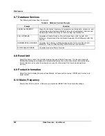
8.2 Routine Maintenance
CAUTION
Calibrate the instrument routinely to ensure conformity to specifications. Calibration is to be performed by
qualified service personnel only.
Clean the front panel with a damp cloth. If needed, use a detergent containing no abrasives. Always clean
the front panel with the bezel closed.
Do not use solvent cleaners.
Failure to comply with these instructions may result in product damage.
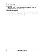
8.3 Set Mode
Select this to change the operating mode to Online or Program.
NOTICE
Changing to ONLINE mode by pressing any of the Display buttons can cause incorrect values to be
displayed. The values will correct themselves in a few seconds. To avoid this potential annoyance, change
to online mode through SET MODE instead of through the Display buttons.
8.4 Calibrate Analog Inputs
Note: the unit must be allowed to warm up for 30 minutes at the intended operating temperature prior to
calibration.
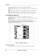
Selecting the CALIBRATE ANALOG INPUTS lists a number of calibration functions you can perform.
Selecting the CALIBRATE ANALOG INPUTS again allows you to specify the AI module and channel in
which to calibrate. When you Select Input, you must apply a 0% reference (low point calibration) value to
the terminal block of the module channel. Then select CALIBRATE to start the calibration routine. After
calibration of 0% value is completed, apply a 100% range value to the channel input terminals and then
begin the calibration routine for 100% input (high point calibration).
When 100% range value calibration is completed, the controller compares the new 0% and 100% range
values against the current 0% and 100% values. If the span of the 0% and 100% readings is less than
20% of the sensor range, the new values are rejected and the current calibration is retained.
Each channel must be calibrated for the specific input type to be applied to that channel. Calibration
values can be copied from one channel to all other channels of like input type and range.
NOTE: Signal generators should have an accuracy of at least 0.05 %. The type of wires depends on the
sensor used. Wait for 5 minutes after that particular sensor is connected (for compensation wires only).
WARNING
In thermocouple pay attention to the ambient temperature. If you are using a mV generator instead of
direct thermocouple generator, the leadwires are in copper and you have to subtract from the mV value
the mV corresponding to the ambient temperature of the rear terminals. (This eliminates the effect of
the cold junction compensation).
Failure to comply with these instructions could result in death or serious injury.
Содержание VRX180
Страница 1: ...Issue 3 03 03 US1I 6228 Video Recorder VRX180 User Manual ...
Страница 2: ...Issue 3 03 03 US1I 6228 ...
Страница 6: ...iv Video Recorder User Manual ...
Страница 48: ...Installation Video Recorder User Manual 34 ...
Страница 222: ...Setpoint Profiler Video Recorder User Manual 208 ...
Страница 234: ...Online Operations Using Primary Displays Video Recorder User Manual 220 ...
Страница 278: ...Appendix A Video Recorder User Manual 264 ...
Страница 290: ...Safety Video Recorder User Manual 276 ...

