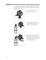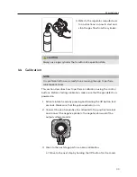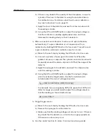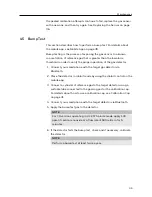
Installation
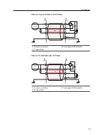
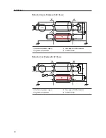
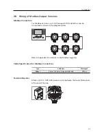
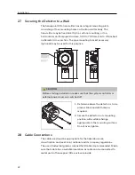
Effective grounding is crucial to ensure stable Modbus
communications and to limit the effects of radio frequency interference.
A ground point is provided inside the housing. In order to prevent false
readings or alarms as a result of ground loops, ensure that the shield of
all cables are grounded at a single point, preferably at the controller.
Consideration should also be given to how conduit and glands.
NOTE
A connection for safety earth is provided at the top of the outside of
the enclosure. This must be used to connect the enclosure to
electrical safety earth. Any earth regime must avoid earth loops.
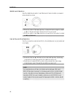
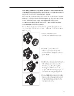
Internal Ground Connection
Utilize the shield of the wiring cable recommended in the wiring
instructions. For connection to this terminal, twist the shield wire to
avoid stray shield wires. Loosen the screw sufficiently and wrap the wire
around the screw in a “U” shape. Raise the clamp and place the wire
between the clamp and ground base, lower the clamp and tighten the
screw to 6.9 lb-in torque (0.78 N·m).
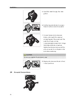
External Ground Connection
If required by local authority, Use a 4 mm
2
copper (stranded or
solid-core) wire to make a connection to this point. Loosen the screw
sufficiently to enable wrapping the wire around the screw in a “U” shape.
Raise the clamp and place the wire between the clamp and ground base,
lower the clamp and tighten the screw to 10.4 lb-in torque (1.17 N·m).
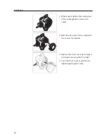
2.10 Finalizing Installation
CAUTION
When installing multiple Sensepoint XRL detectors at the same time,
ensure that the electronics module is kept with its original housing.
If misplaced in any other unit, the detector will not operate properly.
25
Содержание Sensepoint XRL
Страница 1: ...Sensepoint XRL Fixed Gas Detector Instruction Manual ...
Страница 5: ...Contents G Modbus Registers 56 H Contact Information 61 5 ...
Страница 40: ...Appendix A Detector Parameters 40 ...
Страница 61: ...Keep this manual for later use 3017M5023_1 HAA170035 2017 Honeywell Analytics ...

