background image

Appendix

B

Troubleshooting

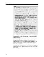
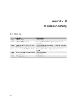
B.1 Warning

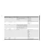
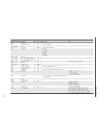
Description

Troubleshooting

Warning 1 Calibration Overdue

Calibrate the unit.

Warning 3 BLE failure (BLE version only)

Power-cycle the unit. If this warning  occurs again, contact the

manufacturer.

Warning 4 Time/date not set (RTC not set) / RTC reset

abnormally

Set the time in the detector using the app. If this warning occurs again,

contact manufacturer.

Warning 5 Log memory corrupted (CRC not matched)

Power-cycle the unit. The event log may be lost if corruption has

occurred.

Warning 6 Certificate is corrupted or missing certificate

Contact manufacturer.

Warning 7 Over-range warning

Calibrate the unit.

Warning 8 Under-range  warning

Calibrate the unit.

44

Содержание Sensepoint XRL

Страница 1: ...Sensepoint XRL Fixed Gas Detector Instruction Manual ...

Страница 2: ...o responsibility for any errors or omissions or their consequences Honeywell would greatly appreciate being informed of any errors or omissions that may be found in the content of this document For information not covered in this document or to send comments or corrections please contact Honeywell using the contact details given on the back page Honeywell reserves the right to change or revise the...

Страница 3: ...d Weight 9 Power Supply 10 Outputs 10 Maximum Power Consumption 10 Operating Environment 11 Recommended Wall Mounting Screws 11 Cable Entry 11 Gas 11 2 Installation 12 2 1 Safety Information 12 2 2 Installation Layout 15 2 3 Power Cable Specification 15 2 4 Main Electronics Module 17 2 5 Wiring of mA Output Versions 17 Power Connection 17 Inhibit Level Selection 18 Current Source Sink Selection 18 ...

Страница 4: ...e Status Indicator 30 4 3 Calibration Cap 31 4 4 Calibration 33 4 5 Bump Test 35 4 6 Replacing the Sensor 36 4 7 Resetting Alarms and Faults 38 5 Mobile App 39 Appendix A Detector Parameters 40 B Troubleshooting 44 B 1 Warning 44 B 2 Fault 45 C Ordering Information 46 C 1 Detectors 46 C 2 Accessories 47 C 3 Consumables 48 C 4 Spares 48 D Warranty 49 E Safety Information for Wireless Devices 50 E 1...

Страница 5: ...Contents G Modbus Registers 56 H Contact Information 61 5 ...

Страница 6: ... on the model Analog output Sensepoint XRL features current loop output supporting signals in the range 0 to 22 mA Typically this interface is referred to as 4 to 20 mA Digital output Sensepoint XRL supports Modbus RTU digital communications Mobile app A mobile app is available to commission and maintain the Sensepoint XRL gas detector 6 ...

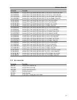
Страница 7: ...r 8 Handle 1 3 Accessories Part number Description SPXRLCAL Sensepoint XRL Calibration Cap SPXRLFLW Sensepoint XRL Flow Housing SPXRLDMK Sensepoint XRL Duct Mount Kit 2308B0923 Pole Mount Bracket Kit SPXCDWP Weather Protection SPXCDCC Collection Cone Order together with SPXCDWP CAUTION All accessories are NOT part of explosion proof certificate 7 ...

Страница 8: ...well Analytics 1 5 Detector Versions The 4 way terminal block s provide connection for both the gas detector output and the power supply Assignment of the terminals and additional terminal blocks will vary dependent on the version Analog mA Output Versions 1 24 V DC or 24 V AC 2 0 V or 24 V AC 3 4 to 20 mA 4 Common For details on wiring for the analog output version see Wiring of mA Output Version...

Страница 9: ...is required to change the configuration settings of the Modbus RTU interface 1 24 V DC or 24 V AC 2 0 V or 24 V AC 3 A 4 B 1 6 Specifications Dimensions and Weight 159 mm 118 mm 93 mm Length 118 mm 4 4 in Height 159 mm 6 2in Depth 93 mm 3 6 in Weight 1400 g 3 1 lb 9 ...

Страница 10: ...ommunication Setting Baud rate 9600 bps Parity None Data bits 8 Stop bits 2 Flow control None Refer to Appendix G for details on the Modbus registers Adjustable Modbus setting Slave ID 1 to 254 Baud rate 9600 19200 bps Parity None Even Odd Maximum Power Consumption The power consumption varies depending on output version and sensor type Power consumption is taken at nominal input voltage Analog Ou...

Страница 11: ...Atmospheric pressure 90 to 110 kPa Installation category II UL CSA IEC EN 61010 1 Pollution degree 2 UL CSA IEC EN 61010 1 Flammable catalytic versions 10 to 90 RH Operating the detector outside of this range may result in increased drift and a reduction in detector accuracy Recommended Wall Mounting Screws Type Countersunk pan head Size 6 mm No 14 diameter 38 mm 1 5 in min Cable Entry ATEX IECEx ...

Страница 12: ... made for adequate grounding and equipment shall be installed in such a manner so that accidental discharge shall not occur When Sensepoint XRL reaches the end of its life it should be disposed of in accordance with local regulations Do not use cleaning solvents or abrasives to clean the gas detector Do not attempt to modify the product in any way from the manufacturers design or specification Warr...

Страница 13: ...tible less than 10 V V Toxic less than 6 V V may suppress the sensor output If using an anti seize compound the threads should be thinly coated with an approved silicone free compound e g petroleum jelly To reduce the risk of ignition of a hazardous atmosphere de classify the area or disconnect the equipment from the supply circuit before opening the detector enclosure Keep assembly tightly closed...

Страница 14: ...allation at the site For Europe see EN60079 29 2 EN60079 14 EN45544 4 and EN61241 14 For installations in North America the National Electrical Code NFPA 70 should be strictly observed All the appropriate local and national regulations should be observed This equipment is designed and constructed as to prevent ignition sources arising even under fault conditions Only the combustible gas detection ...

Страница 15: ...y the characteristics of the gas being detected and other environmental factors Seek advice from experts where necessary CAUTION Sensepoint XRL shall be installed on a flat surface or other suitable structure For installation on a pole or pipe use the official pole mount kit accessory Sensepoint XRL sensor s sinter must be pointing downward 2 3 Power Cable Specification Sensepoint XRL requires a powe...

Страница 16: ...etector is Vcontroller Vdetector min 13 V DC Power consumption of the detector is maximum 2 6 W Wdetector max The maximum current required to drive the XRL at the minimum voltage is 2 6 W 11 V DC 236 4 mA Idetector max So the maximum field cable loop resistance Rloop max is 13 V DC 0 2364 55 Ω Therefore the maximum cable length for any given cable type can be found by dividing the maximum allowable...

Страница 17: ...ltage output 6 Current sink source selection switch 2 5 Wiring of mA Output Versions Power Connection When connecting to DC power make sure that the polarity is correct If AC power is used ensure that terminal 4 Common is used to connect the power and controller grounds together Refer to the circuit diagrams on page 19 and 20 17 ...

Страница 18: ... choose between source mode and sink mode 1 Detector source mode With this switch in the outer position the analog output drives current through the controller sensing circuit 2 Detector sink mode With this switch in the inner position the analog output draws current through the controller sensing circuit NOTE The load resistance of the controller must be between 33 Ω and 250 Ω When the mA output ...

Страница 19: ... 3 4 VE 24 VDC VIN VIN VE 4 20mA 4 20mA RL COM 1 System controller 2 Sensepoint XRL detector 3 Current flow Detector Sink Mode with DC Power 1 2 3 1 2 3 4 VE VIN VIN VE 4 20mA 4 20mA RL COM 24 VDC 1 System controller 2 Sensepoint XRL detector 3 Current flow 19 ...

Страница 20: ...A RL COM COM 24 VAC 1 External power supply 2 Sensepoint XRL detector 3 System controller 4 Current flow Detector Sink Mode with AC Power 1 2 1 1 2 3 4 2 RL 24V DC VE 24 VAC VIN VIN VE 4 20mA 4 20mA COM COM 1 External power supply 2 Sensepoint XRL detector 3 System controller 4 Current flow 20 ...

Страница 21: ...nnected as shown in the diagram below Refer to Appendix G for details on the Modbus registers Cable Specification for Modbus Connection Type Cable Spec Max Length Modbus 0 5 mm2 to 2 5 mm2 twist pair shield cable 1000 m Terminal Resistor Attach a 120 Ω 0 25 W terminal resistor between the A and B terminals at the end of the line 21 ...

Страница 22: ...nstallation make sure that the system controller or external power source is switched off 1 2 0 2 1 Determine where the detector is to be placed Mark and drill holes as required 2 Secure the detector in its mounting position with suitable fixings appropriate to the mounting surface Do not over tighten 2 8 Cable Connections The cable used must be appropriate for the hazardous area classification and ...

Страница 23: ... 0 6 N m Ensure the cable gland is installed correctly and fully tightened All unused cable conduit entries must be sealed with a suitable certified blanking plug 1 2 0 2 1 Unscrew the front cover counterclockwise until it is open 2 Hold the handle of the main electronics module and pull it outward with a steady force Do not pull sharply 3 Pull out the thread protector from the left cable entry and...

Страница 24: ...g to the relevant wiring diagram Strip and insert the end of each wire into the corresponding terminal hole Using a flat blade terminal screwdriver tighten the terminal screw until the wire is secured Use a ferrule on the wire where necessary CAUTION Do not over tighten the terminal screw 8 Replace the terminal blocks in their correct positions 2 9 Ground Connections 24 ...

Страница 25: ...tructions For connection to this terminal twist the shield wire to avoid stray shield wires Loosen the screw sufficiently and wrap the wire around the screw in a U shape Raise the clamp and place the wire between the clamp and ground base lower the clamp and tighten the screw to 6 9 lb in torque 0 78 N m External Ground Connection If required by local authority Use a 4 mm2 copper stranded or solid ...

Страница 26: ... of the cable gland to secure the cable 2 Refit the main electronics module to the connector module pujv t jv 3 Replace the front cover by turning it clockwise ensuring that it is tight 4 Lock the front cover in position by tightening the grub screw 26 ...

Страница 27: ...etector The operating state of the detector is indicated by one of four colors either steady or flashing Normal The indicator flashes green every 20 seconds when the concentration of the target gas is within normal range NOTE Using the mobile Sensepoint app you can change how the green indicator behaves during normal operation Select between confidence flash default setting steady green or off Warning...

Страница 28: ...larm level threshold Out of range alarm The indicator rapidly flashes red when the gas concentration is beyond the full scale deflection of the detector Bluetooth pairing The indicator flashes blue when Bluetooth pairing between the gas detector and an Android device is in progress Bluetooth connected The indicator is on steady blue when a Bluetooth connection is established and the detector is in a ...

Страница 29: ...t 12 months from date of commissioning by an approved Honeywell Analytics representative or 18 months from date of shipment from Honeywell Analytics Sensor 12 months typical Varies dependent on the sensor type 4 1 Using the Control Buttons It is possible to perform basic maintenance functions on the Sensepoint XRL gas detector without the use of the mobile app This is achieved through the use of t...

Страница 30: ...e function can be used at any time during the procedures detailed in the following sections Press and hold the DOWN button for 5 seconds 4 2 Maintenance Status Indicator When performing maintenance such as calibration or sensor replacement using the control buttons refer to the status indicator to determine the status of the detector Inhibit mode While in inhibit mode the indicator is on steady ye...

Страница 31: ...pauses if it fails Calibration gas purge While the calibration gas is purged the indicator is on steady yellow Cancel When a task is cancelled the indicator flashes yellow with three short pauses 4 3 Calibration Cap The following table shows the recommended flow rate and stabilization time for each of the gas types Gas Type Recommended Flow Rate Recommended Stabilization Time O2 500 ml min 5 min CH4...

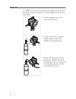
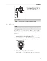
Страница 32: ...ow pujv t jv 1 Push the calibration cap on the sensor cover as shown p u j v t j v 2 Connect a tube from a cylinder of calibration gas to either of the calibration cap s gassing ports p u j v t j v 3 Connect another tube to the other gassing port and place the end of this tube in a position so that gas can exhaust safely away from the work area and other personnel 32 ...

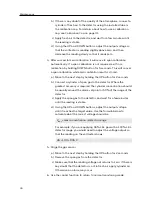
Страница 33: ...scribes how to perform a calibration using the control buttons Before starting calibration make sure that the gas detector is powered on 1 Activate inhibit mode by pressing and holding the UP button for 2 seconds Make sure that the yellow indicator is on 2 Connect the positive probe of a voltmeter to the positive terminal and connect the negative probe to the negative terminal of the output voltag...

Страница 34: ...ds b Connect a cylinder of span gas to the detector Where the greatest accuracy is required the cylinder concentration should be usually around the alarm set point or 50 of the range of the detector c Apply the span gas to the detector and wait for a few minutes until the reading is stable d Using the UP and DOWN buttons adjust the output voltage until it reaches the target value Use the formula b...

Страница 35: ...ith the target gas detector via Bluetooth 2 Place the detector in inhibit mode by using the inhibit control on the mobile app 3 Connect a cylinder of reference gas to the target detector using a suitable tube connected to the gassing port or the calibration cap For details about how to use a calibration cap see Calibration Cap on page 31 4 Connect your smartphone with the target detector via Bluet...

Страница 36: ... attempt to replace the sensor without a removing power to the Sensepoint XRL or b ensuring non hazardous atmosphere and then placing the sensor into the sensor maintenance mode Connect your smartphone to the Sensepoint XRL via Bluetooth Tap the Maintenance button and select Change Sensor Follow the on screen instructions In cases where a smartphone running the mobile app is not available follow t...

Страница 37: ...the sensor socket CAUTION Do not force the sensor into the socket otherwise it may be damaged 8 Press and hold the UP button for 2 seconds to activate warm up mode In this mode the output continues to be held in its inhibit state 9 Replace the sensor cover and tighten the grub screw 10 Switch to normal monitoring mode 11 Perform a calibration in accordance with Calibration on page 33 12 Reassemble...

Страница 38: ...the screen 3 Scroll down to Alarm latching and choose Latching 4 Scroll down to the bottom of the page and tap Apply Settings to save the change When there are latched gas alarm or faults reset them using either of these two methods Use the mobile app to pair with the detector and tap Maintenance Reset Alarm Alternatively press the UP or DOWN button shortly This will reset latched alarms and fault...

Страница 39: ...Serial Number 4 Complete the installation of the detectors 5 On the app s home screen tap DETECTORS to scan for available detectors 6 Select a detector from the detector list to pair with 7 Look for the detector whose Status Indicator is flashing blue 8 Tap Confirm Detector to pair with that detector Otherwise tap Return to list to select one of the others 9 To connect to detectors that are not adde...

Страница 40: ...Appendix A Detector Parameters 40 ...

Страница 41: ... SPLIG1 1000 ppm only 1000 ppm Fixed 500 ppm 105 1 ppm 8 ppm or 20 Gas Sensor Operating Temperature Default Alarm Points Types LAL LDL Min Max A1 Default A1 Type A1 Options A2 Default A2 Type A2 Options Oxygen 20 C 50 C 23 5 vol Rising Rising Disabled 19 5 vol Falling Falling Disabled 5 0 vol 20 6 to 21 2 vol 0 to 3 0 vol Flammable CAT 20 C 50 C 20 LEL Rising Rising Disabled 50 LEL Rising Rising D...

Страница 42: ...the unit in the environment in which it is going to be used Measured test units calibrated at 50 of full scale Measurements are based on gas being applied using the calibration adapter at a rate of 500 ml min for a period of 5 minutes oxygen flammable CAT carbon monoxide hydrogen sulfide 6 minutes hydrogen and 10 minutes nitrogen dioxide Response time T90 may increase when operating in lower tempera...

Страница 43: ...tic bead sensor 4 20 mA output with 250 Ω load resistor To guarantee Sensepoint XRL s long term compliance for UL 2075 at least twice a year 6 months interval gas calibration is required UL 2075 alarm setting of Sensepoint XRL is CO alarms between 60 to 240 min 70 ppm 10 to 50 min 150 ppm 4 to 15 min 400 ppm Methane alarms Less than 25 LEL 43 ...

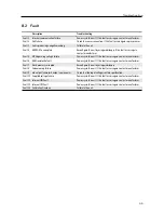
Страница 44: ...Time date not set RTC not set RTC reset abnormally Set the time in the detector using the app If this warning occurs again contact manufacturer Warning 5 Log memory corrupted CRC not matched Power cycle the unit The event log may be lost if corruption has occurred Warning 6 Certificate is corrupted or missing certificate Contact manufacturer Warning 7 Over range warning Calibrate the unit Warning 8 ...

Страница 45: ...t manufacturer Fault 6 RAM read write fault Power cycle the unit If this fault occurs again contact manufacturer Fault 7 Flash memory corrupted Reconfigure the unit by using mobile app Fault 8 Code memory failure Power cycle the unit If this fault occurs again contact manufacturer Fault 9 mA output failure mA output version only Check that the input voltage is within specification Fault 10 Supplied ...

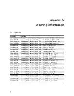
Страница 46: ... Transmitter cULus C1D1 Type 4X H2S L Modbus Charcoal NPT SPLIH1BMXYNUZZ Sensepoint XRL Transmitter cULus C1D1 Type 4X H2S L Modbus Yellow NPT SPLIH2BAXCNUZZ Sensepoint XRL Transmitter cULus C1D1 Type 4X H2S H 4 20 mA Charcoal NPT SPLIH2BAXYNUZZ Sensepoint XRL Transmitter cULus C1D1 Type 4X H2S H 4 20 mA Yellow NPT SPLIH2BMXCNUZZ Sensepoint XRL Transmitter cULus C1D1 Type 4X H2S H Modbus Charcoal ...

Страница 47: ...H2BAXCMAZZ Sensepoint XRL Transmitter ATEX IECEx Ex d IP66 H2S H 4 20 mA Charcoal M20 SPLIH2BAXYMAZZ Sensepoint XRL Transmitter ATEX IECEx Ex d IP66 H2S H 4 20 mA Yellow M20 SPLIH2BMXCMAZZ Sensepoint XRL Transmitter ATEX IECEx Ex d IP66 H2S H Modbus Charcoal M20 SPLIH2BMXYMAZZ Sensepoint XRL Transmitter ATEX IECEx Ex d IP66 H2S H Modbus Yellow M20 SPLIG1BAXCMAZZ Sensepoint XRL Transmitter ATEX IEC...

Страница 48: ...lug M20 SPXRLMAO1 Sensepoint XRL Pluggable Base Electronics Module 4 20 mA O2 SPXRLMAC1 Sensepoint XRL Pluggable Base Electronics Module 4 20 mA CO SPXRLMAH1 Sensepoint XRL Pluggable Base Electronics Module 4 20 mA H2S L SPXRLMAH2 Sensepoint XRL Pluggable Base Electronics Module 4 20 mA H2S H SPXRLMAG1 Sensepoint XRL Pluggable Base Electronics Module 4 20 mA H2 SPXRLMAF1 Sensepoint XRL Pluggable B...

Страница 49: ...e from incorrect handling or use of this equipment In no event shall Honeywell Analytics be liable for any equipment malfunction or damages whatsoever including without limitation incidental direct indirect special and consequential damages damages for loss of business profits business interruption loss of business information or other pecuniary loss resulting from the incorrect installation or use...

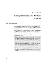
Страница 50: ...sers must follow the specific operating instructions for satisfying RF exposure compliance NOTE This equipment has been tested and found to comply with the limits for a Class A digital device pursuant to part 15 of the FCC Rules These limits are designed to provide reasonable protection against harmful interference when the equipment is operated in a commercial environment This equipment generates ...

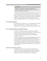
Страница 51: ... E 3 Canada Industry Canada IC Notices This device complies with Industry Canada license exempt RSS Operation is subject to the following two conditions 1 this device may not cause interference and 2 this device must accept any interference including interference that may cause undesired operation of the device This device complies with FCC ISED radiation exposure limits set forth for an uncontrol...

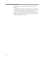
Страница 52: ... limites établies par FCC Industrie Canada en matière d exposition aux radiations dans un environnement non contrôlé Cet équipement ne doivent pas être colocalisés ou fonctionner en conjonction avec tout autre antenne ou émetteur Cet équipement doit être installé et utilisé avec une distance minimale de 20 cm entre le radiateur et votre corps 52 ...

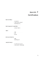
Страница 53: ...ectrical Safety UL 61010 1 CSA C22 2 No 61010 1 IEC EN 61010 1 Electromagnetic Compatibility EN 50270 2015 Radio RED FCC BT SIG Enclosure Protection IP66 NEMA Type 4X Gas Performance UL 2075 CH4 and CO CSA C22 2 No 152 M1984 53 ...

Страница 54: ...r and part number IECEx IECEx UL 17 0038X Ex db IIC T6 Gb Ex tb IIIC T85 C Db Tamb 40 to 65 C cULus Class I Division 1 2 Groups B C and D Class II Division 1 2 Groups E F and G Class I Zone 1 AEx db IIC T6 Zone 21 AEx tb IIIC T85 C IP6X Ex db IIC T6 GbX Ex tb IIIC T85 C DbX Tamb 40 to 65 C Temp Code T6 Specific conditions of use 1 Do not repair flameproof joints 2 See intallation manual for guidance...

Страница 55: ...o reduce the risk of ignition of hazardous atmospheres conduit runs must have a sealing fitting connected within 50 mm of the enclosure Pour réduire le risque d inflammation des atmosphères dangereuses les conduits doivent avoir un joint d étanchéité raccordé à moins de 50 mm de l enceinte Open circuit before removing cover Ouvrir le circuit avant de retirer le couvercle Keep cover tight while circu...

Страница 56: ...on with the gas detector using Modbus RTU over an RS 485 physical layer The Modbus interface provides a means to monitor and interrogate the detector with the addition of being able to reset alarms remotely The Modbus registers for Sensepoint XRL are given in the following table 56 ...

Страница 57: ...15 warning Bit 16 to Bit 31 fault 30020 to 30021 Latched Fault R u32 2 Not used 30022 to 30034 Location Tag R string 26 13 Location tag for BLE scanning 40101 System ID Code R u16 1 MSB always 0x26 to facilitate automatic identification LSB repeat of Modbus address Upper Byte Type Code 0x26 Lower Byte My Address 40102 System ID Code R u16 1 Identical to 40101 Upper Byte Type Code 0x26 Lower Byte My...

Страница 58: ...to facilitate detection of communications prob lems in programming environments where the transport layer communica tion error information is unavailable This increments approximately every 5 seconds It is the responsibility of the system integrator to notify plant personnel if a Modbus master fails to communicate with the Sensepoint XCL XRL This register can facilitate this notification 40109 to 4...

Страница 59: ...1 Transmitter temperature duplicate 40154 Temperature Degrees F R s16 1 40155 Calibration Due R u16 1 Calibration interval DaysPassedSinceLastSuccessfulCal 40156 Relay Status R u8 1 High nibble Relay 2 status Low nibble Relay 1 status 1 Energized 0 De energized 40157 Supply Voltage R f32 2 The voltage supplied to the Sensepoint XCL XRL at the nominal 24 0 volt input in millivolts 40158 Reserved 40...

Страница 60: ...hreshold 1 R f32 2 40169 to 40170 Alarm Threshold 2 R f32 2 40171 to 40172 Target Calibration Gas Concentration R f32 2 40173 Gas Type R u16 1 0x00 Flammable 0x01 Toxic 0x02 O2 0x03 VOC 40174 to 40175 Voltage Output R f32 2 40176 to 40183 Device Serial Number R string 16 8 40184 to 40188 BLE FW Version R string 10 5 BLE FW Version 40189 to 40200 Reserved 40201 Reset Alarms Faults W u16 1 40202 to ...

Страница 61: ...Keep this manual for later use 3017M5023_1 HAA170035 2017 Honeywell Analytics ...

Страница 62: ...ng the details below UK Office Keison Products P O Box 2124 Chelmsford Essex CM1 3UP England Tel 44 0 330 088 0560 Fax 44 0 1245 808399 Email sales keison co uk Please note Product designs and specifications are subject to change without notice The user is responsible for determining the suitability of this product ...

Отзывы: