46
C22UE001-2004
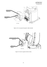
J5-axis Zero-position setting
Step1.
Operate J5 at low speed to align the pinhole of J6 with the pinhole of J5.
Step2.
Insert the calibration tool (A) to the keyway to calibrate Zero-position.
Step3.
Finish the calibration and remove the calibration tool.
Step4.
Clear encoder by HRSS.
Step5.
Zero-position setting of J5-axis is completed.
Figure 4-6
Illustration of J5-axis Zero-position setting
J6-axis Zero-position setting
Step1.
Operate J6 at low speed to align the calibration mark of end effector with the
mark of J6.
Step2.
Clear encoder by HRSS.
Step3.
Zero-position setting of J6-axis is completed.
Figure 4-7
Illustration of J6 -axis Zero-position setting
Calibration mark
Calibration tool(A)
Pinhole
Содержание RA605-710-GC
Страница 1: ...www hiwin tw User Manual Articulated Robot RA605 GC Original Instruction...
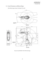
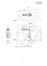
Страница 34: ...33 C22UE001 2004 Figure 2 3 b RA605 909 GC Motion range...
Страница 51: ...50 C22UE001 2004 5 3 Operation Name descriptions of the manual brake release device and their functions...
Страница 68: ...67 C22UE001 2004 8 Appendix Suspension plate refer to section 1 1...


