19
C22UE001-2004
1.2
Installation
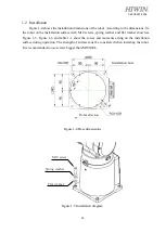
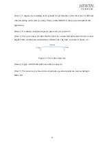
Figure 1-4 shows the installation dimensions of the robot. According to the dimensions, fix
the robot on the installation surface with M10 screws, spring washer and flat washer shown as
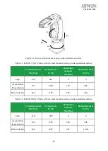
Figure 1-5. Figure 1-6 and table 1-1 show the forces and moments acting on the installation
surface during operation. The strength of surface must be considered when installing the robot.
It is recommended to use screws bigger than M10X20L.
Figure 1-4 Base dimensions
Figure 1-5 Installation diagram
M10 screw
Spring washer
Flat washer
Installation hole
Robot direction
Содержание RA605-710-GC
Страница 1: ...www hiwin tw User Manual Articulated Robot RA605 GC Original Instruction...
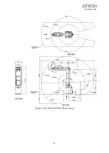
Страница 34: ...33 C22UE001 2004 Figure 2 3 b RA605 909 GC Motion range...
Страница 51: ...50 C22UE001 2004 5 3 Operation Name descriptions of the manual brake release device and their functions...
Страница 68: ...67 C22UE001 2004 8 Appendix Suspension plate refer to section 1 1...


