


8 EXPLANATION OF OPERATION
- 75 -
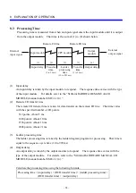
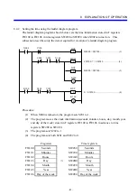
8.1.2 Program execution order
Create a ladder diagram program in such a way that control flows in the order of processing
from the top. Otherwise, much time is wasted, hampering high-speed processing.
Correct ladder diagram program example
Since the ladder diagram program shown below is created in the order in which processing
is performed, its processing is completed within the sequence cycle time.
X000
R000
R001
R002
R000
R001
X000
R000
R001
R002
Sequence cycle time
Incorrect ladder diagram program example
Suppose that processing is programmed in such a way that the conditions to start that
processing are checked after it is actually started. The program requires three sequence
cycles until the processing is started. This wastes two sequence cycle. When the
execution speed of the program is important, carefully consider the processing procedure
during creation of a ladder diagram program.
R001
R002
X000
R000
R000
R001
X000
R002
R001
R000
Sequence cycle time
Содержание S10mini D
Страница 1: ......
Страница 14: ...THIS PAGE INTENTIONALLY LEFT BLANK ...
Страница 19: ...1 BEFORE USE ...
Страница 28: ...THIS PAGE INTENTIONALLY LEFT BLANK ...
Страница 29: ...2 OVERVIEW ...
Страница 34: ...THIS PAGE INTENTIONALLY LEFT BLANK ...
Страница 35: ...3 NAMES AND FUNCTIONS OF PARTS ...
Страница 45: ...4 INSTALLATION ...
Страница 54: ...THIS PAGE INTENTIONALLY LEFT BLANK ...
Страница 55: ...5 WIRING ...
Страница 68: ...THIS PAGE INTENTIONALLY LEFT BLANK ...
Страница 69: ...6 SETTING ...
Страница 84: ...THIS PAGE INTENTIONALLY LEFT BLANK ...
Страница 85: ...7 OPERATION PROCEDURES ...
Страница 91: ...8 EXPLANATION OF OPERATION ...
Страница 111: ...9 MAINTENANCE ...
Страница 128: ...THIS PAGE INTENTIONALLY LEFT BLANK ...
Страница 129: ...10 SPECIFICATIONS ...