REQUIREMENT
Attach a fuse or circuit protector to the external power supply to protect
against short circuits. Use a circuit protector matching the rating of the power
supply.
Verify the wiring before turning on the programmable controller.
Do not shut down (turn off or reset) the programmable controller without
making sure that the peripheral equipment is off or will be unaffected by the
shutdown of the programmable controller.
Memory contents can be corrupted by module failures. Be sure to back up
sensitive data.
See Chapter 1 on page 9.
Secure the mount base to the predetermined vertical surface. If it is secured
to a horizontal surface, heat dissipation would be impeded, resulting in failures
or degraded parts due to temperature rises.
See Chapter 4 on page 32.
Tighten the screws fully. Inadequately tightened screws can cause
malfunctioning, smoking, or firing.
Damage to the module can result from static electricity. Discharge static
charges from your body before setting switches, connecting or disconnecting
the cables, or inserting or removing the connectors.
See Chapter 4 on page 35.
A surge voltage may cause hardware units to malfunction or to be damaged.
When a coil, such as a relay, is connected to the PCs OK output circuit, install
a surge-absorbing diode or similar device. Use a diode with its peak inverse
voltage at least 10 times higher than the circuit voltage and with its forward
current equal to or higher than the load current.
See Chapter 5 on page 43.
Before proceeding with power wiring, make sure that the power cable does not
have a voltage applied to it. Attach the terminal cover immediately upon
power wiring.
Damage to the module can result from static electricity. Discharge static
charges from your body before setting switches, connecting or disconnecting
the cables, or inserting or removing the connectors.
Wire the communications and power cables each separately, particularly at
least 300 mm apart from the power cables for inverters, motors, and power
controllers. Wire the communications and power cables in separate piping or
ducts.
See Chapter 5 on page 49.
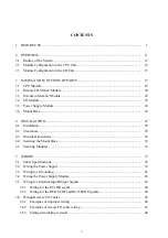
Содержание S10mini D
Страница 1: ......
Страница 14: ...THIS PAGE INTENTIONALLY LEFT BLANK ...
Страница 19: ...1 BEFORE USE ...
Страница 28: ...THIS PAGE INTENTIONALLY LEFT BLANK ...
Страница 29: ...2 OVERVIEW ...
Страница 34: ...THIS PAGE INTENTIONALLY LEFT BLANK ...
Страница 35: ...3 NAMES AND FUNCTIONS OF PARTS ...
Страница 45: ...4 INSTALLATION ...
Страница 54: ...THIS PAGE INTENTIONALLY LEFT BLANK ...
Страница 55: ...5 WIRING ...
Страница 68: ...THIS PAGE INTENTIONALLY LEFT BLANK ...
Страница 69: ...6 SETTING ...
Страница 84: ...THIS PAGE INTENTIONALLY LEFT BLANK ...
Страница 85: ...7 OPERATION PROCEDURES ...
Страница 91: ...8 EXPLANATION OF OPERATION ...
Страница 111: ...9 MAINTENANCE ...
Страница 128: ...THIS PAGE INTENTIONALLY LEFT BLANK ...
Страница 129: ...10 SPECIFICATIONS ...


