


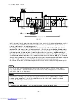
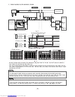
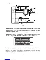


3. Drive circuit of the indoor fan motor
・
The indoor fan motor receives VDC (motor drive power supply), VCC (power supply for the control circuit inside the motor),
and VS (speed command voltage) from CN2. The indoor fan motor returns an FG signal of a frequency that matches the
rotation speed.
・
VCC stabilizes the primary 18.5 V power supply into 15 V by using Q201 and supplies it.
・
While on standby for a remote control signal, the Q201 shuts down the VCC and reduces the standby power.
・
The VS receives a command voltage from the microcomputer (IC601). The VS terminal undergoes an analog voltage that
matches the Lo level time ratio of the pulse signal from pin
$5
of the microcomputer. (See Fig. 3-2.)
・
The FG terminal undergoes a signal of 12 pulses per revolution of the motor shaft. By counting the pulse rate, the
microcomputer (IC601) recognizes the motor speed, thereby performing feedback control.
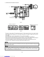
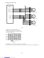
< Typical circuit waveform >
Voltage at pin
$5
of microcomputer (between 0 V and pin
$5
)
FG voltage of fan motor (between pins
④
and
⑦
of CN2)
Relationship between the VS voltage of fan motor
(between pins
④
and
⑥
of CN2) and its rotation
speed (a guide)
When slow
(700min-
1
)
1.7ms.
When fast
(1200min-
1
)
1.7ms.
5V
5V
When slow
(700min-
1
)
7.1ms.
When fast
(1200min-
1
)
15V
15V
4.2ms.
1300min-
1
2.1V
5.4V
Fig. 3-1
Fig. 3-2
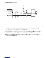
The indoor fan motor and drive circuit are connected to the primary power supply. They therefore have voltage to ground.
Guard against electric shocks.
While the product is energized, do not under any circumstances detach or reattach a connector. Any such practice would
cause a high voltage to run, resulting in the indoor fan motor and board circuit being destroyed. (Check the discharge of
the C003 before detaching or reattaching the connectors.)
Caution
Caution
– 92 –
5
4
7
6
1
M
-
VDC
GN
Indoor fan motor
D
VCC
VS
FG
5V
5V
R20
7
C20
2
R20
4
R23
2
R20
2
C20
1
R23
1
C20
6
R201
Q202
C203
C208
PC20
2
+
+
-
R20
3
12V
0V
R233
C20
5
R23
4
R20
6
R20
5
R211
Q203
D201
Q201
PC23
1
ZD20
2
PC20
3
IC681
CN 2
0V
C63
3
10
7
Primary 280V
Primary 18.5V
Power siganl of
indoor fan(from
pin 57 of
microcomputer)
Primary 0 V
Rotation speed feedback signal (to pin of microcomputer)
Output signal of indoor fan (to pin of microcomputer)
68
45
Содержание RAC-10SH3
Страница 57: ... 55 MODEL RAC 18SH3 Unit mm 580 5 600 345 299 19 5 ...
Страница 60: ... 8 5 WIRING DIAGRAM MODEL RAS 10SH3 3 H S 4 1 S A R 3 H S 8 1 S A R INDOOR UNIT ...
Страница 62: ... 0 6 MODEL RAC 18SH3 OUTDOOR UNIT WHT YEL RED INDOOR UNIT ...
Страница 64: ... 2 6 3 H S 8 1 S A R 3 H S 4 1 S A R 3 H S 0 1 S A R L E D O M ...
Страница 150: ... 8 4 1 MODEL RAC 18SH3 ...
Страница 153: ...HHAW NO 0060E RAS 10SH3 RAC 10SH3 RAS 14SH3 RAC 10SH3 RAS 18SH3 RAC 18SH3 ...