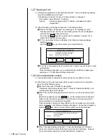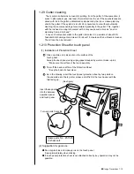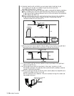
●
Installing Precautions 1-19
(4) The IJ printer main body must be installed with alevelness
error of not over
±
1
°
.
(5) The IJ printer main body must be electrically insulated from
the other equipment
(conveyors, packing machines,etc.), photoelectric switches,
and the rotary encoder.
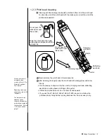
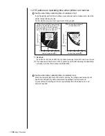
(6) The standard distance between the printing head and the
object to be printed on is as indicated in the right-hand table.
The smaller the clearance between the print head and print
target, the smaller the character height.
(7) The IJ printer proper requires maintenance as the occasion
may demand including replenishment of ink and makeup ink and replacement of filter.
¡
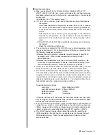
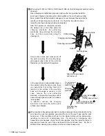
Ensure that there is no flame- or arc-generating device within 5
m of the printer.
The ink and makeup ink are both flammable and may cause ignition
or fire. Flames can be generated by matches, lighters, cigarettes,
heaters, stoves, gas burners, welders, grinders, and static electricity.
Arcs may be generated from open-type relays, switches, and brush
motors. Before handling the ink and makeup ink, remove electricity
from human body, the peripheral equipment, and so on. In the
interests of safety, furnish a dry-chemical fire extinguisher near the
printer.
¡
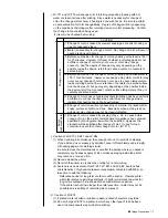
Since the ink and makeup ink contain organic solvents, install
the printer at a location where adequate ventilation (air
exhaust) is provided.
1 Never install the printer in an enclosed space.
2 Connect the printer to exhaust equipment in order to prevent the
organic solvent vapor from being retained.
WARNING
CAUTION
1.4 Installing Precautions
¡
The employed ink and makeup ink contain organic solvents.
Furnish an adequate space for the ink/makeup ink handling area and
printer installation site. A space of at least 200 m
3
must be provided
per print head. Ensure that adequate ventilation is provided.
Follow all regulation in your country.
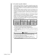
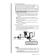
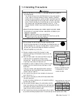
(1) Provide a clearance around the IJ printer for daily
operation, handling, and maintenance access (see the
figure at right).
(2) The print head needs to be cleaned with the makeup ink
while the printer is operated and stopped (daily
maintenance). Adopt a fixed structure in consideration
of print head cover and print head removal.
(3) Installation must be completed so that no vibration will be
applied to the IJ printer main body, print head, or print
head cable.
If they are vibrated, print quality deterioration and print
irregularity may be incurred (the maximum permissible
vibration value is 1.96m/s
2
).
IJ printer
Maintenance area
300
mm
Top view
300
mm
300mm
750mm
Distance between the printing head
and the object to be printed on
Nozzle diameter
65
μ
m
40
μ
m
100
μ
m
Distance
10 to 30mm
5mm
30 to 50mm
※
Leave a maintenance area
of at least 20 cm for the
upside of printer.
Содержание PXR-D
Страница 302: ... Outside Dimensions 13 1 13 Schematic Diagrams 13 1 Outside Dimensions Fig 13 1 Model PXR IJ printer outside dimensions ...
Страница 306: ... Electrical Connection Diagram 13 5 13 2 Electrical Connection Diagram Fig 13 5 Electrical connection diagram ...
Страница 307: ...13 6 Circulation System Diagram 13 3 Circulation System Diagram Fig 13 6 Circulation system diagram ...
Страница 319: ...3S23L1307 3B PXR D E7 HEC ...

