Chapter 3 Programming
3
– 67
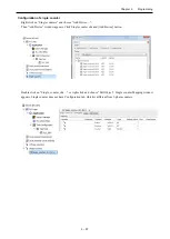
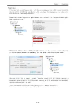
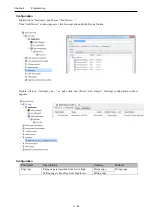
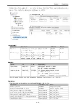
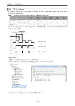
Double click on “Pulse_output_chx…” or right click and choose “Edit Object”. Pulse output configuration window
appears. Pulse output has Configuration tab and Mapping tab as below.
Configuration
Parameter
Descriptions
Choices
Default
Direction
Additional output besides pulse train output can be
used to define direction.
Disable
Disable
Enable
Direction Logic
Forward (Number of pulses = positive) : ON
Reverse (Number of pulses = negative) : OFF
Positive
Positive
Forward (Number of pulses = positive) : OFF
Reverse (Number of pulses = negative) : ON
Negative
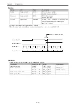
Mapping
Name
I/O
Type
Descriptions
Output status
Input (%IX)
BOOL
TRUE: Pulse train is being output.
FALSE: Pulse train is not output.
Number of pulses
Input (%ID)
DWORD
Accumulated number of pulses is stored.
(position control only)
0 to 4,294,967,295 (direction disabled)
-2,147,483,648 to 2,147,483,647 (direction enabled)
When the number of pulses exceeds the maximum or minimum value, it returns to 0 or 4,294,967,295.
Operations
Pulse train output can be controlled by variables and function blocks as below.
Operations
Variable or FB
Name
Read output status
Variable
Output status (%IX)
Read accumulated number of pulses
Variable
Number of pulses (%ID)
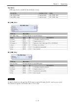
Start pulse train output (position control)
Function block
MV_PLS_Start
Write current position data (position control)
Function block
MV_PLS_Write
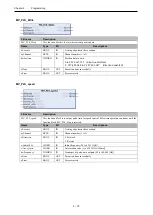
Start pulse train output (speed control)
Function block
MV_PLS_speed
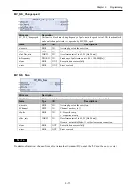
Change speed of pulse train output (speed control)
Function block
MV_PLS_Changespeed
Stop pulse train output
Function block
MV_PLS_Stop
Содержание EH-A14EDR
Страница 6: ...MEMO ...
Страница 10: ...MEMO ...
Страница 141: ...Chapter 3 Programming 3 81 Program ...
Страница 166: ...Chapter 5 Maintenance 5 4 MEMO ...
Страница 170: ...Appendix A1 4 MEMO ...


