Chapter 2 Specifications
2
– 20
No.
Item
Description
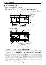
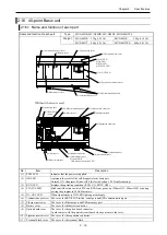
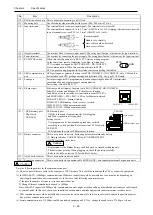
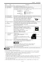
(12) DIN rail installation clip This is used when mounting to a DIN rail.
(13) Mounting hole
Use these holes when installing with screws. (M4×200 mm (0.79 in.))
(14) Input terminals
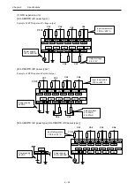
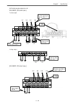
The terminal block to connect input signals. The terminal screw size is M3.
The terminal block supports 0.32 to 2.1 mm
2
(AWG22 to 14). If 2 crimping terminals are connected
to one terminal screw, use 0.32 to 1.3 mm
2
(AWG22 to 16) cable.
(15) Output terminals
The terminal block to connect output signals. The wiring Specification is the same as the input terminal.
(16) Power terminal
The terminal for connecting the power supply. The wiring Specification is the same as the input terminal.
(17) RUN/STOP switch
When this switch position is in RUN, CPU start executing program.
At the same time, remote controlling is enabled, in which case,
CPU is started or stopped by EHV-CODESYS / HX-CODESYS
over communication. When this switch position is in STOP,
CPU stops executing program. In this status, remote controlling is disabled.
(18) USB communication
port
USB port supports gateway function (with EHV-CODESYS / HX-CODESYS) only. USB cable is
not included with CPU package nor supplied by Hitachi-IES. Use type-B USB cable.
(19) Serial port
Serial port supports IEC programming function supporting Modbus-RTU master/slave
communication and general purpose communication.
Port setting is fixed to RS-232C.
(20) Ethernet port
Ethernet port has Gateway function (with EHV-CODESYS /HX-CODESYS),
EtherCAT master and Modbus-TCP client/server function.
In addition, network variables are transferred to/from HX-CPUs
and MICRO-EHV+ PLCs, EHV+ CPUs over Ethernet network.
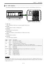
LNK/ACT LED ON : Ethernet link-up
LINK/ACT LED Blinking : Data is sent or received.
100M LED ON : 100Mbps communication
100M LED OFF : 10Mbps communication
(21) - USB memory port
- Dip switch
- USB LED
USB memory port:
USB host function (Program transfer, Data logging
and Web visualization) is supported.
Setting switch:
User program can be downloaded, uploaded or verified
according to switch position. Refer to section 3.22 for details.
USB LED:
LED indicates the status of USB memory function.
(22) Battery connector
This is a connector to battery. Following data are maintained by battery.
(2)
Data specified as VAR RETAIN and VAR PERSISTENT
(2) RTC (real time clock) data
!
Caution
- Replacement of the lithium battery shall be done by a trained technician only.
- The battery has polarity. When plugging in, check the polarity carefully.
- Refer to the table on section 5.2 for the life of battery.
(23) Option board connector
This is a connector to option board.
(24) Expansion connector
This is a connector to expansion cable. MICRO-EHV+ can connect maximum 4 expansion units.
!
Caution
Note the following matters for the communication port.
(1) Do not connect Ethernet cable to the serial port of CPU module. This could cause damage the CPU or connected equipment.
(2) In 100BASE-TX (100Mbps) communication of Ethernet, connection could be unstable due to external noise depending on
cable length, installation environment and etc. In this case, take following countermeasures.
1] Increase the number of times to retry in connected device.
2] Change Ethernet communication speed to 10Mbps.
Since EtherCAT supports 100Mbps only, communication error might occur depending on installation environment, cable length
or external noise. In this case, check your installation environments and take appropriate countermeasures to reduce noise
(3) USB communication could be unstable under severe noise environment. Be sure to use short cable and route apart from power
line or other communication cables.
(4) Serial communication in 115.2kbps could be unstable depending on PC. If so, change the baud rate to 57.6kbps or slower.
6 (0.24)
6 (0.24)
Unit: mm (in.)
Handle very carefully
since cable could be detached
when screw is loose.
(Recommended)
RUN
STOP
Dip switch
USB memory port
USB LED
100M LED
LNK/ACT
Содержание EH-A14EDR
Страница 6: ...MEMO ...
Страница 10: ...MEMO ...
Страница 141: ...Chapter 3 Programming 3 81 Program ...
Страница 166: ...Chapter 5 Maintenance 5 4 MEMO ...
Страница 170: ...Appendix A1 4 MEMO ...

