Chapter 4 Installation
4
– 4
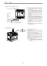
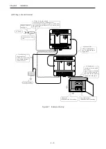
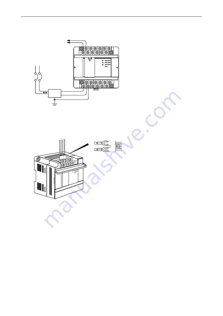
(3) Wiring to the power supply terminal
Power supply for sensors
ELB
100 to 240 V AC
Noise
filter
Isolated
transformer
with shield
Figure 4.4 Wiring power diagram
(a) For power supply wiring, use a cable of 2 mm
2
(0.0031in
2
.) or more to prevent a voltage drop
from occurring.
(b) The function ground terminal (FE terminal)
should use a cable of 2 mm
2
(0.0031in
2
) or more
and Class D grounding (100
Ω
or less). The
appropriate distance for ground cable is within
20m (65.62ft.).
1] Shared with instrumentation panel, relay panel
grounding.
2] Avoid joint grounding with equipment that can
generate noise such as high-frequency heating
furnace, large power panel (several kW or
more), thyristor exchanger, electric welders, etc.
3] Be sure to connect a noise filter (NF) to the
power cable.
(c) The terminal screw size is M3. Recommended
torque is from 0.5 to 0.6 N
・
m (4.4 to 5.3
in.-lbs).
(d) Use the same power supply system for the basic
and expansion units.
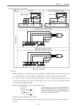
(4) Wiring cable for I/O signals
6
6
The terminal screw size is M3.
Recommended torque is from 0.5 to 0.6 N
・
m (4.4
to 5.3 in.-lbs).
Use a crimp terminal with an outer diameter of
6mm (0.24in.) or less when using it.
Use only up to 2 crimp terminals in the same
terminal. Avoid claming down more than 3 at the
same time.
The terminal block supports 0.32 to 2.1 mm
2
(AWG22 to 14). If 2 crimping terminals are
connected to one terminal screw, use 0.32 to 1.3
mm
2
(AWG22 to 16) cable.
Note: Use shielded cable for the relay output when
corresponding to CE marking EMC command
is necessary.
Содержание EH-A14EDR
Страница 6: ...MEMO ...
Страница 10: ...MEMO ...
Страница 141: ...Chapter 3 Programming 3 81 Program ...
Страница 166: ...Chapter 5 Maintenance 5 4 MEMO ...
Страница 170: ...Appendix A1 4 MEMO ...

