


Configuration Setup
© 2009 Hirschmann Automation and Control GmbH · Branch Office Ettlingen · eMail: [email protected] · www.hirschmann.com
19
24 183 19 1012e (Generic) / 2009-02-26 / Rev. 01 / rk.
•
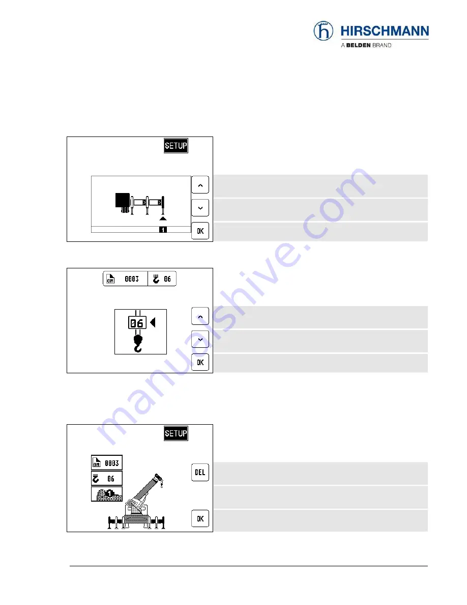
Select
outrigger
position:
(not with man basket operation)
1=max 2=mid 3=min 4=on rubbers
Cursor to next position
Cursor to previous position
Confirm selection, go to next step
•
Select
reeving:
(not with man basket operation)
Increase value
Decrease value
Confirm reeving, go to next step
•
Confirm
inputs:
In this menu screen (example), the operator is prompted to confirm the entries once again.
Please check the displayed values before confirming them!
Discard settings
and renew setup procedure
OK
, only if all entries are correct
The setup procedure is completed after confirmation.
The normal operation screen is displayed.


