


6.2 Saving Data
153
Chapter 6
Managi
ng Dat
a
6
Select
[Yes]
in the confirmation
dialog, and press
ENTER
.
• Numerical calculation must be config-
ured in order to save calculation results
(p. 177)
• When a save span is specified for calcu-
lation results, the results are saved for
the specified span.
Before saving a partial waveform,
specify the span to be saved (p. 140)
Select the save format and
range, select
[Save]
, and press
the
ENTER
key.
Select
[Yes]
in the confirmation dia-
log, and press
ENTER
.
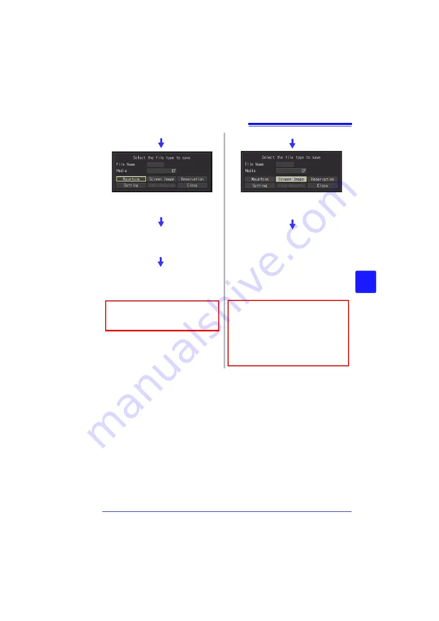
Select
[Waveform]
, and press the
ENTER
key.
Select
[Screen Image]
or
[Calc
Results]
, and press the
ENTER
key.
Содержание MR8880-20
Страница 2: ......
Страница 12: ...Procedure 2 ...
Страница 40: ...1 3 Screen Configuration and Display 30 ...
Страница 76: ...3 4 Measurement Using Setting Wizard PRESETS key 66 ...
Страница 174: ...6 4 Data Management 164 ...
Страница 186: ...7 7 Performing a Printer Check 176 ...
Страница 196: ...8 4 Numerical Value Calculation Expressions 186 ...
Страница 216: ...10 4 Making System Settings 206 ...
Страница 222: ...11 3 Communication Using Commands 212 4Click Next to start install ing Installing Click ...
Страница 226: ...11 3 Communication Using Commands 216 ...
Страница 254: ...13 6 Setting Wizard Function PRESETS 244 ...
Страница 292: ...Appendix 10 Installing Waveform Viewer A30 ...
Страница 297: ......
Страница 298: ......
Страница 299: ......
Страница 300: ......


