30 Crossover Relief Valve Testing & Adjustment
Adjustment:
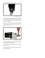
A
B
PHOTO NO. 1000296C
NOTE:
Adjustments should be made in 1/2 turn
increments.
Remove the Allen cap. To adjust port “A” turn
Allen screw or RV2. To adjust Port “B” turn Allen
screw on RV1. The Allen screw underneath the
cap is for adjusting the relief valve pressure set-
ting. Turning the screw clockwise increases the
pressure and turning the screw counterclock-
wise decreases the pressure. Adjust pressure to
relieve at 2100 PSI +/- 100.
NOTE:
If no increase in pressure is observed
when turning the adjustment screw clockwise,
either the pump is weak (see “Hydraulic Pump
Test” page 24), the valve has dirt between the
valve ball and seat, or the spring is weak or bro-
ken. See Removal, Cleaning and Replacement
page 19.
Ensure the Allen cap threads and O-ring are
clean and serviceable and re-install cap.
NOTE:
The System Relief Valve needs to be ad-
justed at this time. See page 31-32.
Содержание DB-7929-1
Страница 2: ......
Страница 4: ...Power Unit Hydraulic POWER UNIT STRAIGHT AND SCOOP PLOW DWG NO 6586 ...
Страница 5: ...Power Unit Hydraulic Circuit Diagram POWER UNIT HYDRAULIC CIRCUIT DIAGRAM DWG NO 4180A ...
Страница 39: ...Notes 33 NOTES ...

