20 Hydraulic Pump Replacement
HYDRAULIC PUMP
REMOVAL, CLEANING AND REPLACEMENT
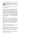
WARNING: Never disconnect any hy-
draulic line or fitting with the unit in
the raised position. Always lower the
unit and relieve pressure before removing
any lines or caps. Allow the system to cool
down before draining oil or handling system
components. Serious burns can result from
contact with hot oil.
SCREW
RESERVOIR
BREATHER
DWG. NO. 3518
Remove breather from reservoir and carefully
drain oil from the reservoir into a suitable con-
tainer. Remove the four retaining screws from
the reservoir with a 1/4” wrench.
PHOTO NO. 1000338
Remove the reservoir while unit is lying flat on
a table. Using a rubber mallet, tap lightly on the
side of the reservoir toward the end.
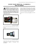
Remove the inlet filter by pulling it straight off
the barbed end of the plumbing elbow. The fil
-
ter should be replaced with a new one (P/N/
25010221).
PHOTO NO. 1000342A
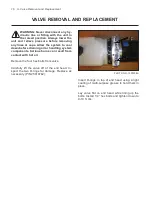
Remove the one bolt from the suction cover us-
ing an E-10 Torx Driver. Remove the remaining
two bolts from the suction cover using a T-30
Torx Driver. Remove suction cover.
PHOTO NO. 1000348
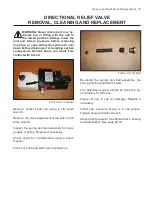
Remove the two bolts from the pump using an
E-10 Torx Driver. Gently pull on the pump to re-
move it from the end head. (
NOTE:
DO NOT
lose magnet.)
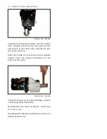
Remove the shaft seal by gently prying it with a
straight slot screwdriver. Discard seal and pump
O-rings and replace with Kit (P/N 25010334).
Содержание DB-7929-1
Страница 2: ......
Страница 4: ...Power Unit Hydraulic POWER UNIT STRAIGHT AND SCOOP PLOW DWG NO 6586 ...
Страница 5: ...Power Unit Hydraulic Circuit Diagram POWER UNIT HYDRAULIC CIRCUIT DIAGRAM DWG NO 4180A ...
Страница 39: ...Notes 33 NOTES ...


