Crossover Relief Valve Replacement 19
DIRECTIONAL RELIEF VALVE
REMOVAL, CLEANING AND REPLACEMENT
WARNING: Never disconnect any hy-
draulic line or fitting with the unit in
the raised position. Always lower the
unit and relieve pressure before removing
any lines or caps. Allow the system to cool
down before draining oil or handling system
components. Serious burns can result from
contact with hot oil.
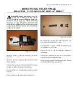
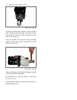
PHOTO NO. 1000296A
Remove socket head cap using a 1/8” Allen
wrench.
Remove the valve adjustment screw with a 3/16
Allen wrench..
Inspect the spring and ball assembly for wear,
gouges or pitting. Replace if necessary.
Check cavity for contamination using a pencil
magnet.
Flush out end head with clean hydraulic oil.
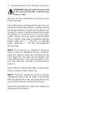
PHOTO NO. 1000304
Re-install the spring and ball assembly, the
spring and the adjustment screw.
The adjustment screw should be turned in ap-
proximately 16 full turns.
Inspect O-ring in cap for damage. Replace if
necessary.
Install cap, ensuring O-ring is in cap groove.
Tighten down with Allen wrench.
Adjust relief pressure. See Relief Valve, Testing
and Adjustment. See page 29-30.
Содержание DB-7929-1
Страница 2: ......
Страница 4: ...Power Unit Hydraulic POWER UNIT STRAIGHT AND SCOOP PLOW DWG NO 6586 ...
Страница 5: ...Power Unit Hydraulic Circuit Diagram POWER UNIT HYDRAULIC CIRCUIT DIAGRAM DWG NO 4180A ...
Страница 39: ...Notes 33 NOTES ...

