Introduction
POWER UNIT OPERATION
GENERAL
The hydraulic power unit DB-7929-1 consists of
a 12 VDC motor, a hydraulic pump rated at 1.3
GPM @ 1600 PSI, and a valve body contain-
ing three electric solenoids, two hydraulic valves
and three adjustable pressure relief valves. The
fluid supply line for the pump is submerged in a
1.5 quart capacity reservoir and is filtered by a
149 micron screen.
The hydraulic power unit DB-7929-2 consists of
a 12 VDC motor, a hydraulic pump rated at 1.75
GPM @ 1600 PSI, and a valve body contain-
ing three electric solenoids, two hydraulic valves
and three adjustable pressure relieve valves.
The fluid supply line for the pump is submerged
in a 1.5 quart capacity reservoir and is filtered by
a 149 micron screen.
The hydraulic power unit DB-7929-3 consists of
a 12 VDC motor, a hydraulic pump rated at 1.75
GPM @ 1600 PSI, and a valve body contain-
ing three electric solenoids, two hydraulic valves
and three adjustable pressure relieve valves.
The fluid supply line for the pump is submerged
in a 1.5 quart capacity reservoir and is filtered by
a 149 micron screen.
The valve body directs hydraulic fluid to oper
-
ate four hydraulic circuits, raise, lower, angle left
and angle right. The angle and lift circuits receive
fluid under pressure, and the lower circuit does
not, however, pressure is generated in the lower
circuit as fluid returns to the reservoir.
Raise Mode Of Operation
Operating the Raise switch energizes the 12
VDC Motor and de-energizes the raise/lower so-
lenoid. Hydraulic fluid under pressure is then di
-
rected through the Neutral position of the angle
left/right spool valve, and a one way check valve
to the lift cylinder.
Releasing the Raise switch de-energizes the 12
VDC motor. The raise circuit is protected by a
pressure relief valve set to relieve system pres-
sure at approximately 2400 PSI Trip and Scoop
Plows, 2000 PSI Home and Steel Straight Plows.
Typically, pressure is relieved when the hydrau-
lic lift cylinder reaches the full up position.
Lower Mode Of Operation
Operating the Lower switch energizes the raise/
lower solenoid, lowers the blade and establishes
a float circuit. The float circuit allows fluid to en
-
ter or exit the raise cylinder allowing the blade to
follow the contours of the ground.
Angle Left or Right Mode Of Operation
Operating the Angle switch energizes the 12
VDC motor and either the angle left solenoid
or angle right solenoid. The angle circuit is pro-
tected by two pressure relief valves (crossover
valves) set to relieve system pressure at ap-
proximately 2100 PSI, Home and Steel Straight
Plow, 2500 PSI, Trip and Scoop Plow and 1600
PSI, 10’ Straight Plow. Typically, pressure is
relieved when the hydraulic angle cylinder (s)
reaches the full left or full right position.
Содержание DB-7929-1
Страница 2: ......
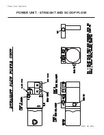
Страница 4: ...Power Unit Hydraulic POWER UNIT STRAIGHT AND SCOOP PLOW DWG NO 6586 ...
Страница 5: ...Power Unit Hydraulic Circuit Diagram POWER UNIT HYDRAULIC CIRCUIT DIAGRAM DWG NO 4180A ...
Страница 39: ...Notes 33 NOTES ...


