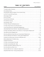
Normally Closed (NC) Release Valve Replacement 15
NORMALLY CLOSED (NC) RELEASE VALVE
REMOVAL, CLEANING AND REPLACEMENT
WARNING: Disconnect Vehicle Bat-
tery prior to performing this procedure
to avoid electrical shock or burns.
WARNING: Never disconnect any hy-
draulic line or fitting with the unit in
the raised position. Always lower the
unit and relieve pressure before removing
any lines or caps. Allow the system to cool
down before draining oil or handling system
components. Serious burns can result from
contact with hot oil.
1
2
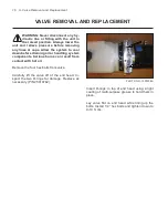
PHOTO NO. 1000322A
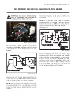
Disconnect the vehicle negative battery terminal
wire (solid black). Disconnect electrical supply to
solenoid coil (blue). Mark or make a note of the
solenoid coil position for reinstallation.
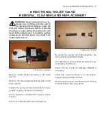
Remove motor terminal nut and remove power
lead (solid red or red-striped).
PHOTO NO. 9014
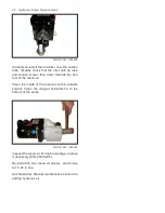
Remove the release valve solenoid nut with a
3/4” wrench. Remove coil from cartridge. Re-
move the release valve cartridge with a 7/8”
deep well socket.
PHOTO NO. 3748
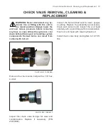
Check cartridge valve for contamination.
Inspect O-rings for wear or damage. With a soft
probe, push in plunger on end of valve. It should
push in approximately 1/16” and spring back.
NOTE:
Doing so should dislodge any foreign ma-
terial holding valve open.
Replace cartridge valve if plunger will not push in
and spring back. (P/N 25010544).
Clean screen by soaking cartridge valve in sol-
vent and inspect end head cavity with a pencil
magnet for contamination. Flush out end head
with clean hydraulic oil.
CAUTION: DO NOT overtighten the coil
nut. The coil and shaft can be easily
damaged requiring replacement.
Re-install the release valve cartridge into end
head and tighten down to 10-15 ft. lbs. Torque
with 7/8” deep well socket.
Re-install coil over the cartridge valve in same
position as noted at time of removal. Tighten
down the release solenoid valve nut to 15-25 in
lbs. Torque with a 3/4” wrench.
Содержание DB-7929-1
Страница 2: ......
Страница 4: ...Power Unit Hydraulic POWER UNIT STRAIGHT AND SCOOP PLOW DWG NO 6586 ...
Страница 5: ...Power Unit Hydraulic Circuit Diagram POWER UNIT HYDRAULIC CIRCUIT DIAGRAM DWG NO 4180A ...
Страница 39: ...Notes 33 NOTES ...

