


HYDRAULIC PUMP TEST
WARNING: Never disconnect any hy-
draulic line or fitting with the unit in
the raised position. Always lower the
unit and relieve pressure before removing
any lines or caps. Allow the system to cool
down before draining oil or handling system
components. Serious burns can result from
contact with hot oil.
TEST CONDITIONS
WARNING: Vehicle engine must be
running for this procedure. Make sure
that there is adequate ventilation in
test area and/or that vehicle exhaust is vent-
ed outside of test area building. FAILURE TO
HEED CAN RESULT IN SERIOUS INJURY OR
DEATH.
- Vehicle battery is fully charged.
- Hydraulic oil level is to “Fill Line.”
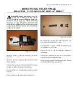
PHOTO NO. 1000387
Remove the hydraulic fitting located at the top
of the U-Valve assembly.
Using the proper fittings, install 0-3000 PSI hy-
draulic pressure gauge in top port of U-Valve.
Turn ignition switch On and hold the joystick in
the Up position. The gauge should be indicat-
ing 2000 PSI + / - 100 PSI, Home Owner and
Steel Straight Plows. 2200 PSI + / - 100 PSI, 10’
Plows. 2400 PSI + / - 100 PSI, Trip and Scoop
Plows.
If gauge indicates less than 2000 + / - 100, test
the following before replacing the pump:
-
Ensure NC Release Solenoid Valve is not
energized when joystick is in the UP posi-
tion with test light or voltmeter.
-
Ensure Adjustable Relief Valve Pressure
setting is correct. See page 31-32.
-
Test DC Motor draw. See page 25.
Replace pump if necessary. See “Hydraulic
Pump Removal, Cleaning and Replacement.”
See page 20-22.
24 Hydraulic Pump Test
Содержание DB-7929-1
Страница 2: ......
Страница 4: ...Power Unit Hydraulic POWER UNIT STRAIGHT AND SCOOP PLOW DWG NO 6586 ...
Страница 5: ...Power Unit Hydraulic Circuit Diagram POWER UNIT HYDRAULIC CIRCUIT DIAGRAM DWG NO 4180A ...
Страница 39: ...Notes 33 NOTES ...