16 U- Valve Removal and Replacement
VALVE REMOVAL AND REPLACEMENT
WARNING: Never disconnect any hy-
draulic line or fitting with the unit in
the raised position. Always lower the
unit and relieve pressure before removing
any lines or caps. Allow the system to cool
down before draining oil or handling system
components. Serious burns can result from
contact with hot oil.
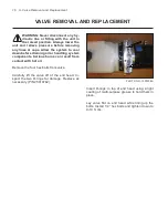
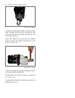
Remove the four hex bolts from valve.
Carefully lift the valve off of the end head. In-
spect the two O-rings for damage. Replace as
necessary (P/N 25010762).
PHOTO NO. 1000308A
Insert O-rings in top of end head using a light
coating of multi-purpose grease to hold them in
place.
Lay valve flat on end head while lining up the
bolts. Install 1/4” hex bolts and tighten down to
9-10 ft. lbs.
Содержание DB-7929-1
Страница 2: ......
Страница 4: ...Power Unit Hydraulic POWER UNIT STRAIGHT AND SCOOP PLOW DWG NO 6586 ...
Страница 5: ...Power Unit Hydraulic Circuit Diagram POWER UNIT HYDRAULIC CIRCUIT DIAGRAM DWG NO 4180A ...
Страница 39: ...Notes 33 NOTES ...


