background image

ID6000 Series Smart Code Reader User Manual 

vi 

Contents 

Chapter 1 Appearance .................................................................................................................... 1


Chapter 2 Interface and Indicator .................................................................................................. 3


2.1 12-Pin Interface................................................................................................................. 3


2.2 Indicator Status ................................................................................................................. 4


Chapter 3 I/O Wiring ...................................................................................................................... 5


3.1 Input Signal ....................................................................................................................... 5


3.2 Output Signal .................................................................................................................... 5


3.3 Input Signal Wiring ........................................................................................................... 6


3.4 Output Signal Wiring ......................................................................................................... 7


3.5 RS-232 Serial Port ............................................................................................................. 8


Chapter 4 Installation ................................................................................................................... 10


4.1 Installation Preparation .................................................................................................. 10


4.2 Install Device ................................................................................................................... 10


4.3 Install Client Software ..................................................................................................... 13


4.4 Turn off Firewall .............................................................................................................. 13


Chapter 5 Network Settings ......................................................................................................... 15


5.1 Set PC Network ............................................................................................................... 15


5.2 Set Device Network ........................................................................................................ 16


Chapter 6 Client Software Layout ................................................................................................. 18


Chapter 7 Camera Settings ........................................................................................................... 21


7.1 Connect Camera to Client Software ................................................................................ 21


7.2 Camera Mode Settings .................................................................................................... 21


7.3 Image Quality Settings .................................................................................................... 22


7.3.1 Set Image ............................................................................................................. 22


7.3.2 Set Light Source .................................................................................................... 24


7.3.3 Set Mirror X .......................................................................................................... 24


7.3.4 Set Test Pattern .................................................................................................... 25


7.4 Barcode Algorithm Settings ............................................................................................ 25


7.4.1 Add Barcode ......................................................................................................... 25


Содержание ID6000 Series

Страница 1: ...ID6000 Series Smart Code Reader User Manual ...

Страница 2: ...Y SPECIAL CONSEQUENTIAL INCIDENTAL OR INDIRECT DAMAGES INCLUDING AMONG OTHERS DAMAGES FOR LOSS OF BUSINESS PROFITS BUSINESS INTERRUPTION OR LOSS OF DATA CORRUPTION OF SYSTEMS OR LOSS OF DOCUMENTATION WHETHER BASED ON BREACH OF CONTRACT TORT INCLUDING NEGLIGENCE PRODUCT LIABILITY OR OTHERWISE IN CONNECTION WITH THE USE OF THE PRODUCT EVEN IF HIKROBOT HAS BEEN ADVISED OF THE POSSIBILITY OF SUCH DAMA...

Страница 3: ...ay cause harmful interference to radio communications However there is no guarantee that interference will not occur in a particular installation If this equipment does cause harmful interference to radio or television reception which can be determined by turning the equipment off and on the user is encouraged to try to correct the interference by one or more of the following measures Reorient or ...

Страница 4: ...oint For more information see http www recyclethis info Industry Canada ICES 003 Compliance This device meets the CAN ICES 3 A NMB 3 A standards requirements Symbol Conventions The symbols that may be found in this document are defined as follows Symbol Description Danger Indicates a hazardous situation which if not avoided will or could result in death or serious injury Caution Indicates a potent...

Страница 5: ...cold dusty environment corrosive environment or high humidity environment Do not aim the product lens at objects of strong light such as the sun and incandescent lamp Otherwise the lens may be damaged The product should be stored in dry environment without corrosive gas Avoid placing the product in direct sunlight and poorly ventilated locations or near heat sources such as heater or heating ignor...

Страница 6: ...ts can be maintained by user please do not disassemble the device arbitrarily Cleaning Please do not touch the image sensor directly If the sensor needs to be cleaned please use a clean rag and wet it with alcohol then gently wipe off the dirt if the camera is not in use please cover the image sensor with dust cover for protection Installation Please do not install the product on vibrating surface...

Страница 7: ...nstallation 10 4 1 Installation Preparation 10 4 2 Install Device 10 4 3 Install Client Software 13 4 4 Turn off Firewall 13 Chapter 5 Network Settings 15 5 1 Set PC Network 15 5 2 Set Device Network 16 Chapter 6 Client Software Layout 18 Chapter 7 Camera Settings 21 7 1 Connect Camera to Client Software 21 7 2 Camera Mode Settings 21 7 3 Image Quality Settings 22 7 3 1 Set Image 22 7 3 2 Set Ligh...

Страница 8: ... 2 Enable Line Inverter 38 7 6 3 Set Event Source 39 7 7 Code Reading Result Settings 47 7 7 1 Set Code Reading Result Output Mode 47 7 7 2 Set Filter Rule 48 7 7 3 Set Result Format 49 7 7 4 Set Cutout 56 7 8 Communication Settings 57 7 8 1 Smart SDK 57 7 8 2 TCP Client 58 7 8 3 TCP Server 58 7 8 4 Serial 59 7 8 5 FTP 59 7 8 6 HTTP 60 7 9 User Set Customization 61 7 10 Indicator Customization 61 ...

Страница 9: ...uto Work 66 Chapter 9 Camera Maintenance 67 9 1 Update Firmware 67 9 2 Reboot Device 67 Chapter 10 FAQ Frequently Asked Question 69 10 1 Why there is no camera listed after I run the IDMVS client software 69 10 2 Why the image is very dark 69 10 3 Why the image quality is very poor during the live view 70 ...

Страница 10: ...anual 1 Chapter 1 Appearance Note Appearance here is for reference only Refer to the device s specification for detailed dimension information 1 2 2 2 2 3 4 2 2 2 2 1 3 4 5 8 7 6 1 Figure 1 1 Appearance Type I Figure 1 2 Appearance Type II ...

Страница 11: ...ten connection between the device and cable and thus avoiding influence caused by vibration 5 PWR Indicator It is the power indicator The indicator is solid blue when the device operates normally 6 LNK Indicator It is network connection indicator The indicator is solid green when the network transmission is normal 7 ACT Indicator It is network transmission indicator The indicator is flashing yello...

Страница 12: ...ply ground 3 OPTO_OUT0 LineOut0 signal line Opto isolated output 0 4 OPTO_OUT1 LineOut1 signal line Opto isolated output 1 5 OPTO_OUT2 LineOut2 signal line Opto isolated output 2 6 OUT_COM LineOut0 1 2 signal ground Common ended output 7 OPTO_IN0 LineIn0 signal line Opto isolated input 0 8 OPTO_IN1 LineIn1 signal line Opto isolated input 1 9 OPTO_IN2 LineIn2 signal line Opto isolated input 2 10 IN...

Страница 13: ...mization to get the method to set specific functions of the custom indicators Table 2 2 Description Device Status PWR Indicator LNK Indicator ACT Indicator U1 U2 Device is powered on Solid blue Solid green Slow fast flashing yellow U1 is unlit and U2 is slow flashing blue Power supply exception Unlit Network exception Solid blue Unlit U1 is unlit and U2 is slow flashing blue Device software except...

Страница 14: ...from 5 VDC to 30 VDC The maximum current is 5 mA Figure 3 1 Internal Circuit of Input Signal 3 2 Output Signal The device s LineOut 0 1 2 is opto isolated output and their internal circuit is as follows Note The input voltage ranges from 5 VDC to 30 VDC The maximum current is 200 mA Do not directly connect with inductive load e g DC motor etc when outputting Figure 3 2 Internal Circuit of Output S...

Страница 15: ...rent types of external devices PNP Device Figure 3 3 Input Signal Connecting to PNP Device NPN Device If the VCC of NPN device is 12 VDC or 24 VDC and pull up resistor is not used its wiring is as follows Figure 3 4 Input Signal Connecting to NPN Device without Pull Up Resistor If the VCC of NPN device is 12 VDC or 24 VDC and 1 KΩ pull up resistor is used its wiring is as follows Figure 3 5 Input ...

Страница 16: ...ernal devices The voltage of VCC should not higher than that of PWR Otherwise the device s output signal may have exception PNP Device Figure 3 6 Output Signal Connecting to PNP Device NPN Device If the VCC of NPN device is 12 VDC or 24 VDC and pull up resistor is not used its wiring is as follows Figure 3 7 Output Signal Connecting to NPN Device without Pull Up Resistor If the VCC of NPN device i...

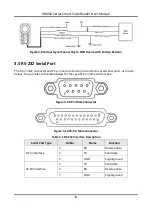
Страница 17: ... commonly used serial ports as shown below You can refer to the table below for the specific pin name and function Figure 3 9 9 Pin Male Connector Figure 3 10 25 Pin Male Connector Table 3 1 RS 232 Interface Description Serial Port Type Pin No Name Function 9 Pin Interface 2 RX Receive data 3 TX Send data 5 GND Signal ground 25 Pin Interface 2 TX Send data 3 RX Receive data 7 GND Signal ground ...

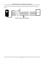
Страница 18: ...an refer to the serial port wiring below to connect the smart code reader with an external device Device Power PWR Device Power Ground External Device GND RS 232 Serial Port Output TX RS 232 Serial Port Input RX GND Figure 3 11 RS 232 Serial Port Wiring ...

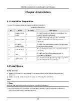
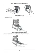
Страница 19: ...to purchase it separately 4 Fixed Bracket 1 It is used to fix the device You need to purchase separately 5 Lens 1 It refers to C mount lens that you need to purchase it separately 6 Light Source 1 It is used to provide light during image acquisition You need to purchase separately 4 2 Install Device Before You Start Make sure the device in the package is in good condition and all the assembly part...

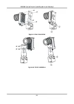
Страница 20: ...ID6000 Series Smart Code Reader User Manual 11 Figure 4 1 Rear Installation Figure 4 2 Front Installation ...

Страница 21: ...tion 2 Use GigE network cable with RJ45 aviation connector to connect the device to a switch or a network interface card Figure 4 4 Gigabit Ethernet Interface Wiring 3 Use power and I O cable to connect the device to a DC switch power supply Figure 4 5 Power and I O Wiring ...

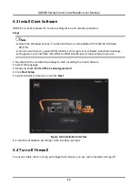
Страница 22: ...allation package The graphic user interface may differ by different versions of client software you use 1 Double click the installation package to start installing the client software 2 Select the language 3 Read and check Terms of the License Agreement 4 Click Start Setup 5 Select installation directory and click Next Figure 4 6 Installation Interface 6 Finish the installation according to the in...

Страница 23: ...Go to Windows Firewall Windows XP system Click Start Control Panel Security Center Windows Firewall Windows 7 system Click Start Control Panel Windows Firewall Windows 10 system Click Start Control Panel System and Security Windows Defender Firewall 2 Click Turn Windows Defender Firewall on or off on the left 3 Select Turn off Windows Defender Firewall not recommended Figure 4 7 Windows Defender F...

Страница 24: ... path and interface may differ Please refer to the actual condition Steps 1 Go to PC network settings page Start Control Panel Network and Internet Network and Sharing Center Change adapter settings 2 Select NIC and set the IP obtainment mode Select Obtain an IP address automatically to get an IP address of the PC automatically Note Enter ipconfig in Run window in your PC and then you can view the...

Страница 25: ...alue may vary from different network interface cards Just set the maximum value if value changes Figure 5 2 NIC Properties Advanced Settings 5 2 Set Device Network You can set and operate the device in the client software only when the device is in the same network segment with the PC where the client software is installed Steps 1 Double click the client software to run it 2 Click to find the devi...

Страница 26: ...ID6000 Series Smart Code Reader User Manual 17 Figure 5 3 Modify IP Address 6 Click OK ...

Страница 27: ...View and Help 2 Control Toolbar The control toolbar provides quick operations for the device You can click different icons to start or stop batch acquisition change window layout view statistics information and device log 3 Device Configuration Area You can connect or disconnect device set parameters and modify device IP address in this area 4 Live View Window This area displays the acquisition im...

Страница 28: ...3 Algorithm Settings You can add different barcodes set barcode number etc 4 I O Control Settings You can set parameters related with input and output 5 Data Processing You can set filter rule for output result 6 Communication Settings You can select different communication protocols and set related parameters for output result 7 Configuration Management You can save and load user parameters and r...

Страница 29: ... 6 3 Select Camera Modes You can click in live view window to view image and code reading effect Note If code reading effect is not very good you can adjust related parameters in Image Settings Figure 6 4 Code Reading In the history area you can view the read time type and content of the recognized barcodes Figure 6 5 History ...

Страница 30: ...ithm Settings for details I O Control Settings It tells you how to set the parameters related to the control of input and output signals of device Refer to Signal Input Settings and Signal Output Settings for details Data Processing It tells you how to set filter rules for reading barcodes and other data processing related parameters Refer to Code Reading Result Settings for details Communication ...

Страница 31: ... displays barcode information Note Before specific camera settings you need to set camera mode as Normal Otherwise the camera parameters may be different 7 3 Image Quality Settings This section introduces how to set image related parameters of the camera via client software Note For different models of the camera the specific parameters may differ and the actual device you purchased shall prevail ...

Страница 32: ...uality Gain You can increase gain to improve image brightness Note To some extent increasing gain will create more image noises and impact image quality Gamma Gamma allows you to adjust the image contrast It is recommended to reduce Gamma to increase brightness in dark background Acquisition Frame Rate Acquisition frame rate refers to the image number that is acquired by the camera per second Acqu...

Страница 33: ...code reading Non Lighting It refers to the device turns off light source during code reading Note If you select Non Lighting as Light Type you do not need to set any parameters If you select External Lighting as Light Type you can set the following parameters Line Out Duration The lighting duration of the external light source and the unit is μs Line Out Delay Time It sets the delay time for light...

Страница 34: ... via the client software In Algorithm Settings you can add different types of barcodes including Code 39 Code 93 Code 128 CodaBar EAN ITF25 QR Code and Data Matrix In Algorithm Settings click Add Barcode select the types of barcodes to be read and set the 1D Code Number and 2D Code Number according to actual demands Note For different models of the camera the specific parameters may differ and the...

Страница 35: ...s corresponding parameters like the maximum running time of algorithm distortion etc Note You should have selected at least one type of 1D code For different models of the camera the specific parameters may differ and the actual device you purchased shall prevail Timeout Value Timeout value refers to the maximum running time of algorithm and its unit is ms The code reader will stop parsing the ima...

Страница 36: ...d the waiting time configured Algorithm Running Mode It is used to be set the algorithm operating mode It includes High Speed High Performance and Balance High Speed focuses on recognition speed and the algorithm can recognize the barcode rapidly while High Performance refers to the algorithm can recognize the barcode that has distortion spot or white gap but its recognition speed is slow Balance ...

Страница 37: ...ent software can recognize the white code with black background Black Code On White Wall means that the client software can recognize the black code with white background Note For QR code the code color is determined by the color of the concentric square on it indicates that the code color is white and indicates that the code color is black Figure 7 6 White QR Code Figure 7 7 Black QR Code For DM ...

Страница 38: ...es dots as the minimum units Adaptive stands for the device can recognize both continuous code and the discrete code QR Distortion Correction If the QR code or DM code is distorted you can enable this parameter to improve code recognition rate Note If you enable this parameter the more time will be consumed to recognize the codes in the image Advance Param This parameter is applicable to some spec...

Страница 39: ...fferent models of the camera the specific parameters may differ and the actual device you purchased shall prevail 7 5 1 Set Trigger Mode The camera has 2 types of trigger modes including internal trigger mode and external trigger mode Internal Trigger Mode In this mode the camera acquires images via its internal signals External Trigger Mode In this mode the camera acquires images via external sig...

Страница 40: ... like software signal and hardware signal You can select different trigger sources set trigger delay time etc Note On refers to the external trigger mode Set and Execute Software Trigger Mode In software trigger the software sends trigger signal to the camera via I O interface to acquire images Steps 1 Click I O Control Settings Input Trigger Mode 2 Select On as Trigger Mode 3 Select Software as T...

Страница 41: ...Level Low as Line Out Trigger In Polarity you can set Start Delay Time and End Delay Time according to actual demands Figure 7 12 Set and Execute Hardware Trigger Mode Set and Execute Counter Trigger Mode Counter specifies that the trigger source will be generated after the set number of valid signals appears For example if you set the Count Number to 3 the trigger source will be generated after 3...

Страница 42: ...d select TCP Start as Trigger Source Set Trigger Delay Tcp Trigger Port and Tcp Start Trigger Text according to actual demands Figure 7 14 Set and Execute TCP Trigger Mode Set and Execute UDP Trigger Mode UDP start specifies the UDP server as the source for the trigger signal When the server receives the specified string text the trigger signal will be outputted Click I O Control Settings Input Tr...

Страница 43: ...g text the trigger signal will be outputted Click I O Control Settings Input Trigger Mode select On as Trigger Mode and select Serial Start as Trigger Source Set Trigger Delay Serial Baudrate Serial Data Bits Serial Parity Serial Stop Bits and Serial Start Trigger Text according to actual demands Figure 7 16 Set and Execute Serial Port Trigger Mode 7 5 4 Stop Trigger The device supports stopping t...

Страница 44: ...rigger Figure 7 17 Stop Trigger via IO When selecting SoftwareTriggerEnd as IO Stop Trigger Selector you can click Execute in Software Stop Trigger to stop current trigger Figure 7 18 Software Trigger End Stop Trigger via Serial When the specified serial port receives the specified string text the trigger will be stopped The client software sends stop trigger command to the device after Serial Sto...

Страница 45: ...ver receives the specified string text the trigger will be stopped The client software sends stop trigger command to the device after Udp Stop Trigger Enable is enabled You should enter Udp Trigger Port and Udp Stop Trigger Text according to actual demands The range of Udp Trigger Port is from 1025 to 65535 and the default port is 2002 Figure 7 20 Stop Trigger via UDP ...

Страница 46: ...n the camera mode is set to Normal and the Trigger Mode is On When the trigger time reaches the specified maximum value in ms the trigger will be stopped You can enable TimeOut Stop Trigger Enable and set Maximum Output Limited Time according to actual demands The range of Maximum Output Limited Time is 0 to 10000 ms Figure 7 22 Stop Trigger via Timeout Duration Stop Trigger via Max Code Number No...

Страница 47: ...ck I O Control Settings Output Line Out Selector to select output signal Figure 7 24 Select Output Signal 7 6 2 Enable Line Inverter The level inverter function allows the camera to invert the electrical signal level of an I O line and meets requirements of different devices for high or low electrical signal level You can go to I O Control Settings Output Line Out Inverterto enable it Note The Lin...

Страница 48: ...to the event source you select Click I O Control Settings Output Line Out Activation Event to select event source The device supports following event sources including Off AcquisitionStartActive AcquisitionStopActive Frame BurstStartActive FrameBurstStopActive ExposureStartActive SoftTriggerActive HardTriggerActive CounterActive TimerActive NoCodeRead ReadSuccess LightStrobeLong and LightContinued...

Страница 49: ...e output signal will be triggered When you select AcquisitionStartActive as Line Out Activation Event you can set its output delay time and duration Line Out Delay Time It sets the delay time for outputting the output signal Line Out Duration It sets the time duration of the output signal Figure 7 27 Select Acquisition Start Active ...

Страница 50: ...sets the time duration of the output signal Figure 7 28 Select Acquisition Stop Active Select Frame Burst Start Active Note The Frame Burst Start Active is not supported when the trigger polarity is level high or level low If the burst of a frame starts the output signal will be triggered When you select Frame Burst Start Active as Line Out Activation Event you can set its output delay time and du...

Страница 51: ...ity is level high or level low If the burst of a frame stops the output signal will be triggered When you select Frame Burst Stop Active as Line Out Activation Event you can set its output delay time and duration Line Out Delay Time It sets the delay time for outputting the output signal Line Out Duration It sets the time duration of the output signal Figure 7 30 Select Frame Burst Stop Active ...

Страница 52: ...on Line Out Delay Time It sets the delay time for outputting the output signal Line Out Duration It sets the time duration of the output signal Figure 7 31 Select ExposureStartActive Select Soft Trigger Active If you select Soft Trigger Active as Line Out Activation Event you can set its output delay time duration and execute outputting signal manually Line Out Delay Time It sets the delay time fo...

Страница 53: ...nd trigger activation Line Out Delay Time It sets the delay time for outputting the output signal Line Out Duration It sets the time duration of the output signal Hardware Trigger Source It sets the hardware trigger source including LineIn 0 LineIn 1 and LineIn 2 Hardware Trigger Activation It sets the trigger activation of input signal including Rising Edge Falling Edge Level High and Level Low F...

Страница 54: ...r outputting the output signal Line Out Duration It sets the time duration of the output signal Figure 7 34 Select Counter Active Select Timer Active If you select Timer Active as Line Out Activation Event you can set its output duration period and execute outputting signal manually Line Out Duration It sets the time duration of the output signal Line Out Period It sets the time period of the outp...

Страница 55: ...me It sets the delay time for outputting the output signal Line Out Duration It sets the time duration of the output signal Figure 7 36 Select No Code Read Select Read Success If you select ReadSuccess as Line Out Activation Event you can set its output delay time and duration Line Out Delay Time It sets the delay time for outputting the output signal Line Out Duration It sets the time duration of...

Страница 56: ... mode and non instant output mode Instant output mode means that the device can instantly output code reading results when recognizing codes if you enable Instant Output Mode Enable in Filter Rule Non instant output mode means that the device does not output code reading results it recognized until the trigger stops if Instant Output Mode Enable is not enabled If the device does not recognize any ...

Страница 57: ...om 1 to 256 For example if you set the value as 6 the device will not parse the contents of the barcodes which contain less than 6 characters Max Code Length If the length of a barcode is longer in terms of the number of characters contained in the barcode than the configured value the device will not parse the contents of the barcode The valid value is from 1 to 256 For example if you set the val...

Страница 58: ...ing results of a barcode is same for the configured times the barcode will be regarded as valid and its reading result will be outputted Or the barcode will be regarded as invalid and its reading result will not be outputted Figure 7 38 Set Filter Rule When the camera mode is Normal and trigger mode is Off you can set Filter Time during which the device will not output code information Besides you...

Страница 59: ...to set any parameter NoRead Image Index It sets the specific image that is outputted when no barcode information is read For example if you set this parameter as 5 and the 5th image will be output Figure 7 39 Result Output via Smart SDK Result Output via TCP Client When the communication protocol is TCP Client camera mode is Normal and trigger mode is On you need to set following parameters in the...

Страница 60: ...art of the data outputted You can set the contents according to actual condition Tcp Output Stop Text The contents of the end part of the data outputted You can set the contents according to actual condition Tcp Output TcpDelimiter It refers to the delimiter that separates barcode name position angle package ID etc You can set it according to actual condition Figure 7 40 Result Output via TCP Clie...

Страница 61: ...the barcode TcpServer Output Barcode Angle Enable If this parameter is enabled the outputted barcode information will contain the angle of the barcode TcpServer Output Barcode MainPackageID Enable If this parameter is enabled the outputted barcode information will contain the package ID TcpServer Output NoRead Enable If this parameter is enabled when no barcode is recognized the device will output...

Страница 62: ...pecific image that is outputted when no barcode information is read For example if you set this parameter as 5 and the 5th image will be output Serial Output Barcode Name Enable If this parameter is enabled the outputted barcode information will contain the name of the barcode Serial Output Barcode Position Enable If this parameter is enabled the outputted barcode information will contain the posi...

Страница 63: ...mode is Normal and trigger mode is Off you can set Serial Output Barcode Name Enable Serial Output Barcode Position Enable Serial Output Barcode Angle Enable Serial Output Barcode MainPackageID Enable Serial Output Start Text Serial Output Stop Text and Serial Output Delimiter Result Output via HTTP When the communication protocol is HTTP camera mode is Normal and trigger mode is On you just need ...

Страница 64: ...ion is reached the retransmission will be discarded Ftp Transmission Conditions It sets the condition to upload the data outputted by the device to FTP server All refers to upload the data always Read Barcode refers to upload the data only when the barcode is read by the device No Read Barcode refers to ppload the data only when no barcode is read by the device Ftp Transmission Result Contain It s...

Страница 65: ...ed in the file name Take YYYYMMDD_HHMMSSFFF as an example from the left to the right YYYY represents year MM represents month DD represents date HH represents hour MM represents minute SS represents second and FFF represents millisecond Figure 7 44 Result Output via FTP When the communication protocol is FTP camera mode is Normal and trigger mode is Off you cannot set NoRead Image Index Others par...

Страница 66: ...result and image The communication protocol is related to the device modes With various device modes the device supports different communication protocols and corresponding parameters When the camera mode is Test or Raw the device only supports Smart SDK protocol and no parameter settings are required While in Normal mode the device supports Smart SDK TCP Server TCP Client Serial FTP and HTTP comm...

Страница 67: ...he the images When the server returns to normal the device will send the cached images to the server After this parameter being enabled you can setOutput Result Buffer Number to determine the number of the images that the device will cache You can also enable TCP Protocol enter TCP Dst Addr and TCP Dst Port Figure 7 47 TCP Client 7 8 3 TCP Server The TCP includes TCP Server and TCP Client If selec...

Страница 68: ...unication Protocols you need to set following parameters Output Result Buffer If enabled when the FTP server is abnormal the device will cache the images When the FTP server returns to normal the device will send the cached images to the server After this parameter being enabled you can set Output Result Buffer Number to determine the number of the images that the device will cache You can also yo...

Страница 69: ...s the Communication Protocols you can enable HTTP Server enter HTTP Sever Port and WebRefresh Cycle HTTP Server If enabled the device will output data via HTTP server HTTP Server Port Enter the port No of the HTTP server WebRefresh Cycle Set the frequency to refresh the Web Figure 7 51 HTTP ...

Страница 70: ...ce to the saved group of parameter values again if required Go to Config Management Load Settings and click Default UserSet1 UserSet2 or UserSet3 to load settings Note The Default refers to restore the device parameter settings to the factory ones Start Settings The selected user set will be automatically loaded after the device being powered on For example if you select Default the device paramet...

Страница 71: ...m I you can click Execute to let indicators flash and know which device you are operating 4 System Running The indicators flash once when the device system operates 5 Be Triggered The indicators flash once when the device receives trigger signals 6 LineOut 0 The indicators flash once when LineOut 0 outputs signals 7 LineOut 1 The indicators flash once when LineOut 1 outputs signals 8 LineOut 2 The...

Страница 72: ...d before camera operation 8 1 Live View Live view allows you to view the image in real time Click in live view window to start live view or click to stop Figure 8 1 Live View 8 2 Enable Acquisition Enabling acquisition allows the device to acquire streams from the device in real time Click in live view window to start acquisition or click to stop You can also right click the device on the device l...

Страница 73: ...w to add cross line and click beside to open the editing window to set cross line parameters Figure 8 3 Add Cross Line 8 4 Start Recording During live view you can record video files and capture images continuously Note Enabling acquisition is required before recording Click in live view window to start recording and click the icon again to stop You can also click beside and then click to capture ...

Страница 74: ... click Custom to customize window division as you desired Figure 8 5 Split Window 8 6 View Reports During acquisition or live view you can view the reading status of the device Click in control toolbar to open the statistics window to view the detailed information Read Code Images refers to the number of the images on which the barcodes are read by the device Unread Code Images refers to the numbe...

Страница 75: ...ow and you can view different types of logs including device errors warning and informational log etc Figure 8 7 View Log 8 8 Enable Camera Auto Work This function allows the device to automatically enter the operating status after being powered on You can go to Config Management Device Auto Work Enable and enable Device Auto Work Enable Figure 8 8 Enable Camera Auto Work ...

Страница 76: ...vice will reboot automatically after updating the firmware Select the device to be updated in the device list right click the device and click Firmware Update Click to select update file from local PC and click Update to update firmware Note You can also go to Tool Firmware Updater to update firmware Figure 9 1 Update Firmware 9 2 Reboot Device You can reboot the device via client software in 2 wa...

Страница 77: ...ID6000 Series Smart Code Reader User Manual 68 Figure 9 2 Reboot Device ...

Страница 78: ...e is powered up normally Check the network connection observe whether the top LNK light is flashing green or not to make sure the device can be connected to the network normally PC port and the device are in the same network segment 10 2 Why the image is very dark Problem All black or too dark during preview Reason Insufficient brightness of supplement light Too small adjustment value of exposure ...

Страница 79: ...ring the live view Problem The image quality is very poor during the live view Reason The network may be fast Ethernet Incorrect jumbo packet setting Solution Confirm whether the network transmission speed is 1 Gbps and NIC is the gigabit NIC etc Set jumbo packet value as 9 KB or 9014 bytes ...

Страница 80: ...UD20319B ...

Отзывы: