ID6000 Series Smart Code Reader User Manual
2
Table 1-1 Description
No.
Name
Description
1
Lens Cap
It refers to the device’s lens cap.
Note
The type II device does not have the lens cap.
2
Screw Hole
It is used to fix the device to installation position. It is
recommended to use M4 screw.
3
Gigabit Ethernet
Interface
It refers to gigabit Ethernet interface for transmitting
data.
4
12-Pin Interface
It provides power, input/output, and serial port signal.
The interface is designed with screw threads to tighten
connection between the device and cable, and thus
avoiding influence caused by vibration.
5
PWR Indicator
It is the power indicator. The indicator is solid blue when
the device operates normally.
6
LNK Indicator
It is network connection indicator. The indicator is solid
green when the network transmission is normal.
7
ACT Indicator
It is network transmission indicator. The indicator is
flashing yellow when the network transmission is
normal. The indicator flashing speed is related with data
transmission speed.
8
U1/U2 Indicator
The device has 2 user-defined indicators, U1 and U2.
They are used to indicate whether some functions of the
device are normal or not.
9
Lens Mount
It is used to install the lens.
Содержание ID6000 Series
Страница 1: ...ID6000 Series Smart Code Reader User Manual ...
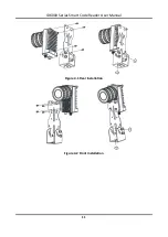
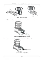
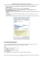
Страница 20: ...ID6000 Series Smart Code Reader User Manual 11 Figure 4 1 Rear Installation Figure 4 2 Front Installation ...
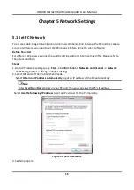
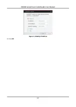
Страница 26: ...ID6000 Series Smart Code Reader User Manual 17 Figure 5 3 Modify IP Address 6 Click OK ...
Страница 77: ...ID6000 Series Smart Code Reader User Manual 68 Figure 9 2 Reboot Device ...
Страница 80: ...UD20319B ...


