Installation
Suprasetter A52/A75 – Installation
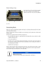
Format setting on tray
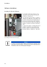
Fig. 77 Tray
Concluding Work
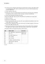
Bypass the safety loop with the key-operated switch prior to switching on the Suprasetter and switch
on the Suprasetter only then.
Perform a visual check of the laser module for any coolant leaks once the chiller has started circulat-
ing the coolant.
Remove the key-operated switch and fit the casing back on:
• Secure the USB stick again to its original position in the Suprasetter using a cable tie (or other
suitable material) (Fig. 62).
Fit the rear panel (Fig. 3).
• Heed the direction of the brackets during hood installation. The brackets point to the outside. Fit
the cover (Fig. 7 and Fig. 11), remove the service pushbutton if used, and plug the connector of
the operating button to X206.
• Install the front cover (Fig. 2).
Switch on the Suprasetter. With the Suprasetter switched off, check that the laser module is seated
correctly (unhook spring / reposition module / tighten spring again) if an error message about the
laser module displays after initialization of the Suprasetter.
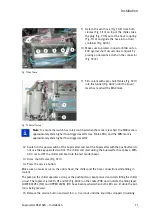
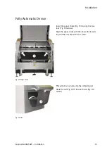
Insert the tray (Fig. 77/1) and set the format guides
(Fig. 77/2) according to the size required. The
maximum format that can be set is 530 X 505mm.
NOTICE
Beware of short circuit
Do not tilt the laser module while the Suprasetter is switched on.
Содержание Suprasetter A52
Страница 6: ......
Страница 24: ...Safety 22 Fig 24 Filter replacement Fig 13 4 On the filter unit ...
Страница 26: ...Safety 24 Fig 26 Warning sign copy template ...
Страница 36: ...Installation Preparation 34 Pallet Installation Instructions ...
Страница 60: ...Installation 58 Fig 51 Power cable strain relief Tighten the strain relief for the power cable Fig 51 1 ...
Страница 82: ...Technical Data 80 Resolution 1000 pixels cm 2540 dpi Type Value Comment ...
Страница 84: ......
Страница 85: ......

