2-4 Examining operating conditions
83
1
2
3
4
5
6
7
8
9
10
11
付
S
e
le
c
tion gui
de
lin
e
s
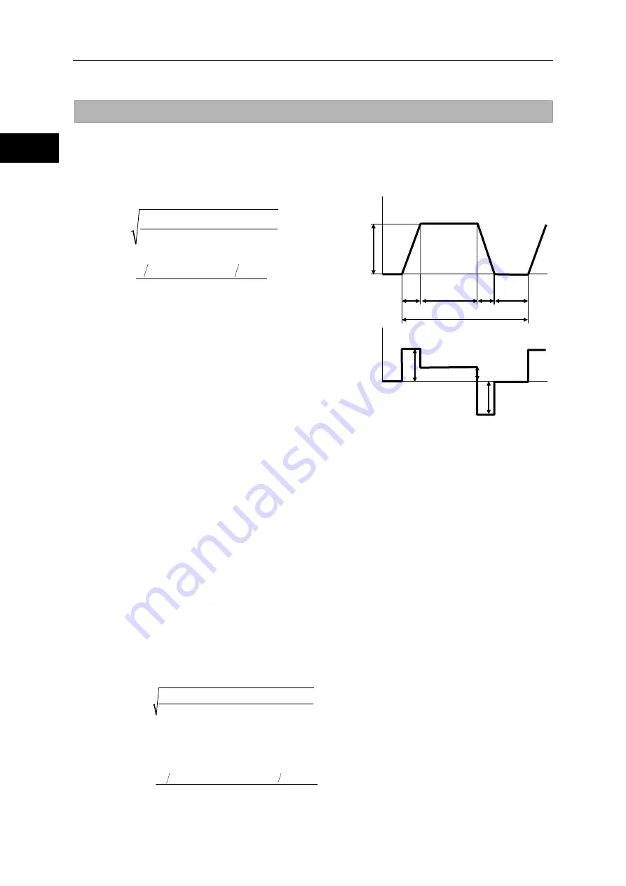
Examining effective torque and average rotation speed
One way to check if the heat generated from the actuator during operation would present a problem is
to determine if the point of operation, determined by the effective torque and average rotation speed,
is inside the continuous motion range explained in [1-14 Operable range].
Using the following formula, calculate the effective torque T
m
and average rotation speed N
av
when
the actuator is operated repeatedly in the drive pattern shown to the right.
t
a
:
Acceleration time from speed 0 to N
(
s
)
t
d
:
Deceleration time from speed N to 0
(
s
)
t
r
:
Operation time at constant speed N
(
s
)
t :
Cycle time
(
s
)
T
m
: Effective torque (Nm)
T
a
: Torque during acceleration (Nm)
T
r
: Torque at constant speed (Nm)
T
d
: Torque during deceleration (Nm)
N
av
: Average rotation speed (rpm)
N :
Rotation speed at constant speed (rpm)
Calculation example 2
An example of SHA25A51SG-B09A200 is explained.
Operating conditions: Accelerate an inertia load and then let it move at a constant speed,
followed by deceleration, based on conditions similar to those used in calculation example 1.
The travel angle per cycle is 120° and the cycle time is 1 second.
(1)
The travel angle is calculated from the area of the rotation speed vs. time diagram shown
above. In other words, the travel angle is calculated as follows:
θ
= (N / 60) x {t
r
+ (t
a
+ t
d
) / 2} x 360
Accordingly, t
r
=
θ
/ (6 x N) – (t
a
+ t
d
) / 2
When
θ
= 120°, and t
a
= 0.177 (s), t
d
= 0.141 (s), N = 80 (rpm) in calculation example 1,
are applied to this formula, t
r
is calculated as 0.091 (s).
(2)
Next, calculate the torque during acceleration and torque during deceleration. Based on the
acceleration/deceleration time formulas in the preceding section, the relational expressions
for torque during acceleration and torque during deceleration if k = 1 are as follows:
T
a
= (J
a
+J
L
) x 2 x
π
/
60 x N /
t
a
+ T
L
T
d
= (J
a
+J
L
) x 2 x
π
/
60 x N /
t
d
– 2 xT
F
– T
L
When the values in calculation example 1 are applied to this formula, T
a
= 98 (Nm) and T
d
=
90 (Nm) are obtained.
(3)
Calculate the effective torque. Apply the values in (1) and (2), and T
r
= 0 (Nm) and t = 1 (s),
to the above formulas.
(4)
Calculate the average rotation speed. Apply the values in (1), and N = 80 (rpm) and t = 1 (s),
to the above formulas.
Time
ta
td
N
tr
Time
Rotation speed
t: Cycle time
ts
Ta
T
or
que
Td
Tr
ts: Stopped time
Ta, Tr, Td: Output torques
t
t
T
t
T
t
T
T
d
2
d
r
2
r
a
2
a
m
×
+
×
+
×
=
t
t
2
N
t
N
t
2
N
N
d
r
a
av
×
+
×
+
×
=
Nm
53
1
0. 141
90
0. 091
0
0. 177
98
T
2
2
2
m
=
×
+
×
+
×
=
r /mi n
20
1
0. 141
2
80
0. 091
80
0. 177
2
80
N
av
=
×
+
×
+
×
=
Содержание SHA CG Series
Страница 1: ...AC Servo Actuator SHA SG and CG series manual ISO14001 Hotaka plant ISO9001...
Страница 93: ...Chapter 4 Options This chapter explains the options available for the SHA series actuator 4 1 Options 94...
Страница 95: ...Options 95 1 2 3 4 Apx 6 7 8 9 10 11 Appendix Outline drawing of the actuator with an optional stand Nameplate...
Страница 100: ...Options 100 1 2 3 4 Apx 6 7 8 9 10 11 Appendix Appendix A 1 Unit conversion 101 A 2 Calculating inertia moment 103...
Страница 107: ......


