Vista FX
1-4 Vista FX
Document generated: 28.08.14
SW V4.9
2
Hardware
The Vista FX hardware is coming in a housing which uses 2 RU in a 19” rack.
It has the Studer partnumber
5003726
.
One such hardware unit is the equivalent of two Lexicon PCM96 “engines”.
Up to three such Vista FX units can be combined, to provide Lexicon effects
in the equivalent of six Lexicon PCM96.
Front LED’s
The faceplate provides a green and a red LED for each of the redundant pow-
ersupplies, “Power1” and “Power2”. The green LED indicates ‘ok’ state of the
powersupply, the red LED indicates the ‘fail’ state, in case of a powersupply
failure or in case of a loss of power.
Connectors
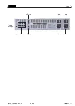
On the rear of the unit the following connectivity is provided :
• 2x mains inlet with switches for redundant power supplies
• 8x RJ45 HD-Links for audio connection to the dsp engine as well as slave
units.
• 4x RJ45 Ethernet Control Ports (A and B). Two of each for daisy chaining.
Number of Slaves switch
A rotary switch allows to set the “Number of Slaves” (the number of addition
-
ally Vista FX units, connected to the “Master” unit). Range :
0..2
.
Lock LED’s
These LED’s inform about the HD-Link Lock status of the audio connections.
A solid illuminated LED means that the HD-Link is locked, and therefore
the audio connection is established and ok. While the unit is booting and the
audio connection is being established, the LED is flashing. When the LED
stays dark, no connection is established or the Lock status has been lost. (e.g.
due to the connected unit being powered down, or an error in the HD-Link
connection).
Core/Master
LED - Status of the HD-Link to the DSP Core
Slave1
LED - Status of the HD-Link to the first Vista FX slave unit
Slave2
LED - Status of the HD-Link to the second Vista FX slave unit
Slave3
LED - currently not used.

