background image

54

7. Operation (continued)

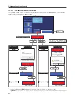
7-1-11-1 

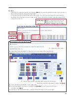
Flowchart (Screen Button Operation)

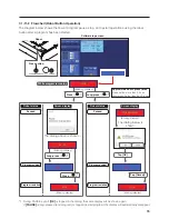
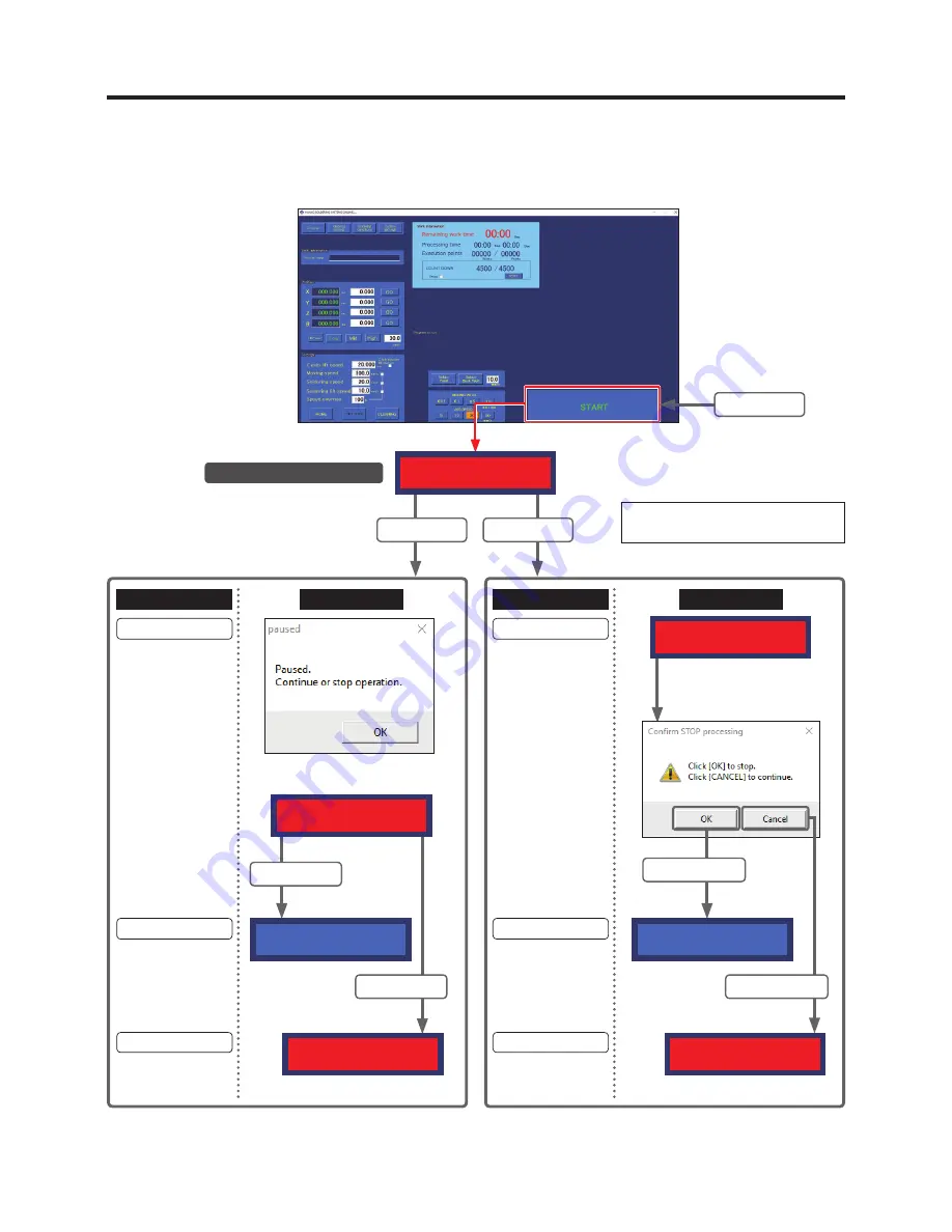
The diagram below shows the flow of program pause, stop, and restart operations using the screen 

buttons after a program has been started.

Software top screen

While program is running

Long press

Tap

Long press

(Blinking display)

The set time for long press can be 

checked in the PC’s setting screen.

*1  During PAUSE, even if 

[OK]

 is tapped in the dialog, the same display will be shown again. 

If 

[PAUSE]

 is long-pressed (end program) or tapped (restart program) the display will automatically disappear.

STOP

The dialog above is shown.

*1

The dialog below is 

shown.

Robot status

Robot status

Screen display

Screen display

Paused

Paused

(Blinking display)

(Blinking display)

Program ended

Program ended

Program restarted

Program restarted

Long press

Tap

STOP

(Blinking display)

STOP

(Blinking display)

Tap [OK].

Tap [Cancel].

START

START

PAUSE

STOPPING (PC)

Содержание HU-200

Страница 1: ...HU 200 is a soldering robot system This manual explains how to use the HAKKO HU 200 and the software Be sure to read this manual before operating the HAKKO HU 200 Keep this manual readily accessible...

Страница 2: ...llation 19 5 2 Attaching Accessories to the Robot 19 5 2 1 Attaching the Feeder Unit CX5005 20 5 2 2 Attaching the Soldering Iron Unit 21 5 2 3 Attaching Tube Units 26 5 2 4 Connecting Cables and Cord...

Страница 3: ...Creating a Solder Feed Program Solder Feed Parameter Setting Screen 71 7 4 2 2 Reading Writing Soldering Conditions 72 7 5 Creating a Soldering Program 73 7 5 1 PS Point Soldering Settings 74 7 5 2 D...

Страница 4: ...ldering Iron Unit HAKKO FU 601 120 8 1 3 Feeder Unit CX5005 120 8 1 4 Soldering Unit Fixture Base CX5002 121 8 1 5 Jig Table 121 8 1 6 Soldering Unit Mount CX5004 122 8 1 7 Cleaner Base CX5003 122 8 2...

Страница 5: ...5003 1 p 4 Feeder unit CX5005 p 4 Solder reel support shaft p 2 Feeder cable 4 m BX1045 1 p 2 Tube unit 0 3 1 0 BX1055 p 2 Tube unit 1 2 1 6 BX1042 p 2 Tube unit B 0 3 BX1054 p 2 Tube unit B 0 5 1 0 B...

Страница 6: ...ion and Connection 1 Quick user guide PC software 1 I O cable for cleaner 1 Attachment holder 1 1 Display arm 1 1 Relay cord 1 5m 1 HAKKO HU 200 robot USB cable BX1062 Feeder cable 4 m BX1045 Quick us...

Страница 7: ...30 2 Soldering iron cable 5 m BX1033 Tip adjustment jig unit For TX1 series tips CX5017 For TX2 series tips CX5018 Feeder unit attachment screw HAKKO FU 6002 FU6002 01X Relay cord BX1056 Soldering uni...

Страница 8: ...to Tip Types in the instruction manual of HAKKO FU 601 3 Solder feed pulley units solder feed guide sets and Teflon tubes are sold separately For further details refer to 11 Parts List p 134 1 5 Solde...

Страница 9: ...able position accuracy X 0 01 mm Y Z 0 01 Allowable voltage range AC100 240V 50 60Hz 5 Noise level 56dB Operating environment Ambient temperature range 0 40 C No condensation or freezing Ambient humid...

Страница 10: ...Solder back feed length 0 20 0 mm Solder back feed speed 0 99 9 mm Heat time 0 1 9 9 sec 1 Depending on the type of solder it may not be possible to feed solder normally at high speed In such cases c...

Страница 11: ...600 650 910 200 190 83 6 231 261 263 91 400 412 442 Center of cleaning position Loadable workpiece dimensions according to cleaning position X axis stroke Y axis stroke Z axis stroke 720 excluding pro...

Страница 12: ...8 2 Specifications continued 2 2 2 Jig Table 250 230 150 100 50 250 230 150 100 50 81 M4 screws Units mm...

Страница 13: ...ation of a safety enclosure to prevent workers from entering the robot s range of movement during operation Safety enclosure If there is no safety enclosure indicate the robot s range of movement and...

Страница 14: ...of a dangerous condition perform work within reach of an emergency stop button or install emergency stop devices close at hand If a dangerous situation occurs press the emergency stop button button o...

Страница 15: ...wet hands or use the product when the main body or cords are wet If the product becomes abnormally hot or emits smoke abnormal odors or abnormal noise stop use immediately and set the power switch to...

Страница 16: ...of the battery However the duration of the charge varies depending on the use environment and ambient temperature CAUTION If the battery runs out the position information for each axis will be lost an...

Страница 17: ...to Software as a part of Software and the terms and conditions of the Agreement shall remain in effect Licensee may terminate the Agreement by uninstalling or destroying Software In case Licensee brea...

Страница 18: ...ensor shall not be liable for any damages or lost profit caused to Licensee directly or indirectly from use or inability of this product including operation of a machine or Software caused from such u...

Страница 19: ...is Head cover Solder reel holder Cleaner base Attachment holder Display arm axis Door cover Front panel Y axis Jig table Easy Input Switch JOY STICK for Z axes JOY STICK for X Y axes START PAUSE STOP...

Страница 20: ...se button is pressed while the equipment is in emergency stop condition while the application is running the solenoid brake will be set to off CAUTION There is a danger of the Z axis dropping when the...

Страница 21: ...ion details see 7 2 JOG Operation p 56 Easy Input Switch button Pressing the Easy Input Switch will set the current coordinates as the soldering start point or end point For operation details see 7 4...

Страница 22: ...or for FU 601 Power switch main power supply Outlet 1 Outlet 2 for cleaner and PC Motor connector for feeder 4 4 Rear Panel CAUTION Even if the cable is plugged into a USB connector other than the USB...

Страница 23: ...structions to each other to ensure safety and prevent dangerous contact or falls Secure the robot in place to prevent the robot from tipping over or falling CAUTION Since the door cover of the JOY STI...

Страница 24: ...e careful not to overtighten the screws The attachment method of the solder feed pulley unit for 0 3 mm solder BX1000 is different Refer to Solder setting method included with the BX1000 2 Remove the...

Страница 25: ...screws included with the soldering unit mount 3 Attach the soldering unit mount CX5004 to the soldering unit fixture base CX5002 using 4 of the hexagon socket head cap screws included with the solderi...

Страница 26: ...soldering unit mount the right tension spring supports the soldering unit mount CX5004 feeder unit CX5005 and HAKKO FU 6002 and the left tension spring supports the feeder unit CX5005 and HAKKO FU 60...

Страница 27: ...ON Be sure to attach the soldering unit fixture base in the proper orientation Attach in the orientation shown in the following diagram while paying attention to the hexagon socket head cap screw moun...

Страница 28: ...t resistant pad 1 Slide the spatter prevention cover forward 2 Loosen the tip holding screw M3 10 3 Insert the tip 4 Tighten the tip holding screw 5 Cover with the spatter prevention cover CAUTION Che...

Страница 29: ...s c Loosen screw d Adjustment screw Jig fixture Jig base Alignment pins 2 Loosen screws c Flange socket M3 10 2 Cover screws M4 12 2 2 Loosen screws c and d and place the HAKKO FU 6002 on the tip adju...

Страница 30: ...Install the solder bobbin while paying attention to the solder feed direction 2 Open the cable clip on the upper part of the soldering unit fixture base CX5002 pass the tube unit through the cable cli...

Страница 31: ...r unit CX5005 and tighten the screws indicated in the diagram 4 Close the feeder unit cover Tube unit 0 3 1 0 mm BX1055 1 2 1 6 mm BX1042 Tube unit B 0 3 mm BX1054 0 5 1 0 mm BX1052 1 2 1 6 mm BX1053...

Страница 32: ...ed guide and the Teflon tube attachment method For adjustment method details refer to 7 4 1 Solder Installation and Solder Feed Position Adjustment p 68 6 Attach tube unit B and the solder feed guide...

Страница 33: ...00 robot and the feeder unit and tube unit B attached between the feeder unit and the solder feed guide There are different models of each kind according to the solder diameter Tube unit 0 3 1 0 mm BX...

Страница 34: ...cord HAKKO HU 200 set between the HAKKO FU 601 and robot 2 Connect the soldering iron cable BX1033 between the HAKKO FU 601 and HAKKO FU 6002 Feeder cable BX1045 Relay cord To HAKKO FU 601 HAKKO HU 2...

Страница 35: ...USB cable BX1062 and power cord 5 2 6 Connecting the Power Cord for robot Insert the power cord for robot into AC IN at the back of the robot USB cable BX1062 Power cord for PC Power cord for cleaner...

Страница 36: ...information on how to use the cleaner CX1003 refer to the cleaner instruction manual DC IN IN Vs 1 DC IN IN Vs GND Hexagon socket head cap screw M3 6 4 Loosen Adjust position X axis direction Loosen H...

Страница 37: ...the product during use XG4C 4031 CN6 N24 0 V P24 IN0 IN2 IN4 IN6 1 3 5 7 9 11 13 15 17 27 29 31 33 35 37 39 19 21 23 25 2 4 6 8 10 12 14 16 18 28 30 32 34 36 38 40 20 22 24 26 OUT0 OUT2 OUT4 OUT6 OUT8...

Страница 38: ...s in order to install the software 6 1 Performing a New Installation of the Software 1 Double tap on 2 Select the language to be used for the installation 3 After selecting the language tap OK to proc...

Страница 39: ...lect I accept the terms in the license agreement and tap Next CAUTION Installation and use of this software can be performed only by agreeing to this Software License Agreement If agreement to the End...

Страница 40: ...he desktop and copy the following two folders as backup data Program folder containing soldering program data System folder containing cleaning setting data For information on backing up soldering con...

Страница 41: ...older to under C Hakko Corporation HAKKO SOLDERING SYSTEM2 and overwrite the existing System folder If the existing folder is not overwritten with the backup copy cleaning settings will be the initial...

Страница 42: ...ton of the HAKKO HU 200 robot and switch on the power of the PC When the PC is switched on the sign in screen will appear When first shipped from the factory it is possible to proceed without inputtin...

Страница 43: ...nger in the surrounding area When HAKKO SOLDERING SYSTEM2 starts each axis will move as the robot returns to the origin Be careful to stay out of the way of the robot as it moves When the axis rotates...

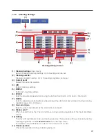
Страница 44: ...are starts up the top screen including the following information will be shown 1 Program 7 Settings 2 Cleaning Settings 8 JOG operation settings 3 Soldering Conditions 9 Solder Feed Solder Back Feed 4...

Страница 45: ...area of the top screen 5 BAR CODE Calls up the Bar Code Setting Screen The PWB to be worked on and the created program can be linked For details on the Bar Code Setting Screen refer to 7 7 3 Calling u...

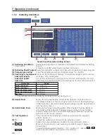
Страница 46: ...ked indicates that the start point is an offset Z Checked when Return to is set to Z lift position P Shows the solder feed soldering condition number D If checked indicates that the soldering mode is...

Страница 47: ...and end point STEP 4 Y axis start point and end point Settable ranges X axis 0 400 mm Y axis 0 300 mm SP Start point EP End point Solder point number 1 Close the error screen 2 Open the Point Edit Sc...

Страница 48: ...he work origin Set the post copy workpiece origin in advance and select the X axis and Y axis values for the set work origin 9 As shown in the above figure tapping the beginning of a row will cause th...

Страница 49: ...put Switch button When checked the setting destination will be automatically switched each time the robot s Easy Input Switch button is pressed Soldering mode 1 For PS mode End point Start point Next...

Страница 50: ...for Z lift position movement will be vertically to the Z axis lift position 16 Palletizing When checked palletizing settings can be performed Palletizing is used when the settings for a created point...

Страница 51: ...ective cleaning times while waiting at the start point and end point during cleaning Settable range 0 0 60 0 sec 8 Use current pos Sets the current coordinates as the start point or end point 9 Disabl...

Страница 52: ...lder back feed speed 0 99 9 mm Heat time 0 1 9 9 sec 1 For secondary and tertiary soldering all values can be set starting from 0 5 Solder Feed Button for manually feeding solder When tapped it will b...

Страница 53: ...ER HEAD ANGLE Set the angle matching the mounting angle of the soldering iron unit The tip angle can be changed between 0 and 60 and mounted Refer to diagram at right 7 SOLDER UNIT Connects to the HAK...

Страница 54: ...the program being run 5 COUNT DOWN Left value Shows the value equal to the set value minus the number of executed points When the count reaches 0 the program will pause even if the program is in the...

Страница 55: ...ng coordinate movement of the robot 1 Shows the current coordinate of the robot for each axis 2 When the coordinates to move to are known input the coordinates When GO is tapped the corresponding axes...

Страница 56: ...s will be moved first and then the X Y and axes will be moved in that order 7 DRY RUN Performs the robot motion of the selected program without adjusting the soldering iron temperature or performing s...

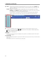
Страница 57: ...to 7 1 3 Soldering Conditions p 48 and for operations refer to 7 4 Solder Installation and Solder Feed Settings p 68 7 1 10 Running Program 7 1 11 Start Button Program start pause stop and restart ope...

Страница 58: ...C s setting screen 1 During PAUSE even if OK is tapped in the dialog the same display will be shown again If PAUSE is long pressed end program or tapped restart program the display will automatically...

Страница 59: ...Long press button less than 0 6 sec 1 During PAUSE even if OK is tapped in the dialog the same display will be shown again If PAUSE is long pressed end program or tapped restart program the display wi...

Страница 60: ...in the message window Note Even if OK is tapped before the emergency stop button has been returned to its normal position the same display will appear again Perform the emergency stop button operation...

Страница 61: ...Select Ex Low Low etc speed first and be careful of contact 2 Input the X Y Z and coordinates to move to into the respective spaces Settable range X 0 400 mm Y 0 300 mm Z 0 200 mm 200 3 Tapping GO ne...

Страница 62: ...ected Speed JOY STICK operation If the coordinates are unknown or if you want to move the robot freely movement of axes can be performed using the JOY STICKS inside the door cover of the robot 1 Selec...

Страница 63: ...ustments when adjusting tip position etc the axis can be moved using the inching function Refer to diagram below 1 Select the desired INCHING PITCH 0 01 mm deg 0 1 mm deg 0 5 mm deg or 1 0 mm deg in t...

Страница 64: ...damage to the PWB and areas around where soldering is performed The Z axis lift coordinate is a coordinate setting for avoiding contact with protruding objects on the workpiece during horizontal move...

Страница 65: ...ill be stopped at the point where the Z axis is moved from a position higher than the Z axis lift coordinate to a position lower than the Z axis lift coordinate While a program is running if the Z axi...

Страница 66: ...In order to avoid the protruding object when moving from the 3rd point to the 4th point the Lifting Pos is set to 75 mm in the Point Edit Screen of the 4th point Z axis lift is performed from the 3rd...

Страница 67: ...ning process and the angle can be set Cleaner CX1003 Start point End point Start point Brush Tap Cleaning Settings in the top screen and input the settings 1 Move the tip to a position where cleaning...

Отзывы:

Похожие инструкции для HU-200