45
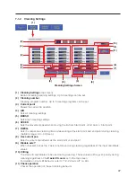
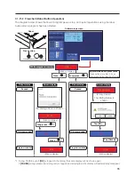
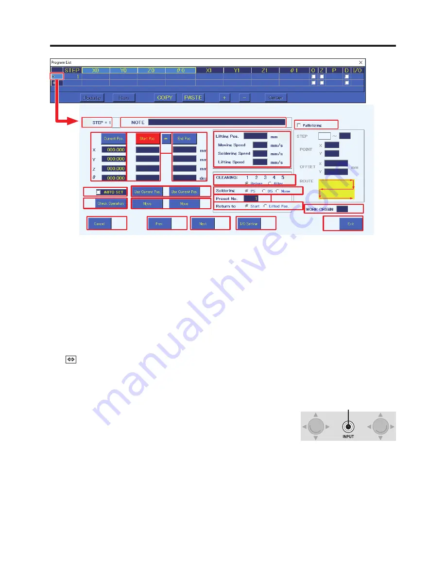
Point Edit Screen
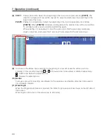
Detailed point settings are performed in the Point Edit Screen.
(1) STEP = 1
(number)
1 (number) indicates the solder point number.
(2) NOTE
Comments, memos, etc. for each point can be input.
(3) Current Pos.
Shows the current tip position.
(4) Start Pos./OFFSET
Sets the coordinates or offset amount of the start point.
When
[Start Pos.]
is shown, tapping
[Start Pos.]
will switch to
[OFFSET]
, and when
[OFFSET]
is
shown, tapping
[OFFSET]
will switch to
[Start Pos.]
.
(5)
Switches between setting the coordinates read using the robot’s
[Easy Input Switch]
button or
[Use Current Pos.]
as the start point/offset or end point.
(6) End Pos.
Sets the coordinates of the end point.
(7) AUTO SET
Reads coordinates using the robot’s
[Easy Input Switch]
button.
When checked, the setting destination will be automatically switched
each time the robot’s
[Easy Input Switch]
button is pressed.
Soldering mode
*1
For PS mode: End point
→
Start point
→
Next point
For DS mode: Start point
→
End point
→
Next point
For None: Start point
→
Next point
For PS mode (Offset): End point (Automatic offset input
*2
)
→
Next point
*1 For details about soldering mode, refer to “(13) Soldering” on the next page.
*2 The automatically input offset amount is set in the System Settings Screen.
For details about system settings, refer to “7-1-4 System Settings” (p. 49).
(8) Use Current Pos.
Sets the current coordinates as the start point or end point.
When the start point is an offset, sets the offset value of the System Settings Screen.
(9)
Check Operation
The operation of the steps set in this screen will be simulated.
(2)
(1)
(3)
(4)
(6)
(7)
(9)
(8)
(10)
(11)
(12)
(13)
(14)
(15)
(16)
(17)
(18)
(19)
(20)
(21)
(22)
(5)
[Easy Input Switch]
button

