38
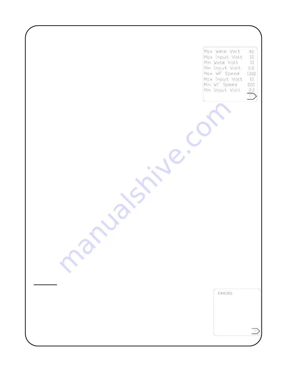
Example: For the screen shown to the right it was determined the welding power source being
used had a welding voltage range of 1- 40 volts, it was also verified that the remote analog
control signal for welding voltage was 0-10 VDC.
Information for the wire feed speed showed that the standard wire
feeder that is normally used with this power source had a speed range
0 to 1000 IPM (inch per minute), it was also verified that the remote
analog control signal wire feed speed was 0-10 VDC.
Note:
the wire feed speed will represented in either inch per
minute of cm per minute depending on the unit calibration of the control.
Max Weld Volt:
This allows the operator to set the upper (maximum) welding voltage. The
adjustable range is 0 to 99 volts in increments of 1. Factory set at 40 volts.
Max Input Volt:
This allows the operator to set the upper (maximum) threshold of the 0-10VDC
signal to achieve the maximum welding voltage. The adjustable range is 0 to 10 volts in
increments of 0.1 Factory set at 10 volts.
Min Weld Volt:
This allows the operator to set the lower (minimum) welding voltage. The
adjustable range is 0 to 99 volts in increments of 1. Factory set at 10 volts.
Min Input Volt:
This allows the operator to set the lower (minimum) threshold of the 0-10VDC
signal to achieve the minimum welding voltage. The adjustable range is 0 to 10 volts in
increments of 0.1 Factory set at 0.0 volts.
Max WF Speed:
This allows the operator to set the upper (maximum) wire feed speed. The
adjustable range is 0 to 1000 IPM [2540 cm/min] in increments of 1. Factory set at 1000 IPM
[2540cm/min].
Max Input Volt (WF):
This allows the operator to set the upper (maximum) threshold of the 0-
10VDC signal to achieve the maximum wire feed speed. The adjustable range is 0 to 10 volts in
increments of 0.1 Factory set at 10 volts.
Min WF speed:
This allows the operator to set the lower (minimum) wire feed speed. The
adjustable range is 0 to 1000 IPM [2540 cm/min] in increments of 1. Factory set at 0 IPM [0
cm/min].
Min Input Volt (WF):
This allows the operator to set the lower (minimum) threshold of the 0-
10VDC signal to achieve the minimum wire feed speed. The adjustable range is 0 to 10 volts in
increments of 0.1 Factory set at 0.0 volts.
Screen 4:
Error Code Screen:
Whenever the Pipe KAT encounters a problem that
triggers an error code the error will be displayed on the main screen of the
display. In addition the errors will be stored on this screen. This screen is
useful in the event that more than one (multiple) error codes have be
triggered, all errors triggered will be displayed on this screen to allow the
operator to trouble shoot the cause(s).
Содержание Pipe Kat PK-500-LG Series
Страница 2: ......
Страница 3: ...i ...
Страница 4: ......
Страница 46: ...42 Screen 2 Screen 2 Screen 3 Screen 3 Screen 4 Screen 4 Screen 5 Screen 5 44 2 112 633 1608 ...
Страница 52: ...48 REVISION LIST July 2012 Manual release ...
Страница 53: ......
Страница 54: ...www GULLCO com ...


